


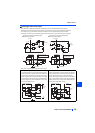
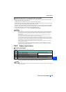
Control circuit
INSTALLATION AND WIRING
41
2
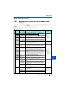
NICHIFU Co.,Ltd.
NOTE
• When using stranded wires without a blade terminal, twist enough to avoid short circuit with a nearby terminals or wires.
• Never change the control logic while power is ON.
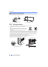
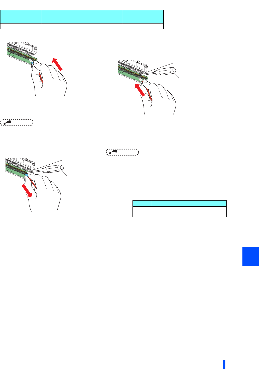
•Wire removal
Common terminals of the control circuit (SD, PC, 5, SE)
• Terminals SD (sink logic), PC (source logic), 5, and SE are common terminals (0V) for I/O signals. (All common terminals
are isolated from each other.) Do not earth (ground) these terminals. Avoid connecting the terminal SD (sink logic) with 5,
the terminal PC (source logic) with 5, and the terminal SE with 5.
• In the sink logic, terminal SD is a common terminal for the contact input terminals (STF, STR, STOP, RH, RM, RL, JOG, RT,
MRS, RES, AU, CS) and the pulse train output terminal (FM
). The open collector circuit is isolated from the internal
control circuit by photocoupler.
• In the source logic, terminal PC is a common terminal for the contact input terminals (STF, STR, STOP, RH, RM, RL, JOG,
RT, MRS, RES, AU, CS). The open collector circuit is isolated from the internal control circuit by photocoupler.
• Terminal 5 is a common terminal for the frequency setting terminals (2, 1 or 4) and the analog output terminals (AM, CA
).
It should be protected from external noise using a shielded or twisted cable.
• Terminal SE is a common terminal for the open collector output terminals (RUN, SU, OL, IPF, FU). The contact input circuit
is isolated from the internal control circuit by photocoupler.
Terminal FM is provided in the FM-type inverter.
Terminal CA is provided in the CA-type inverter.
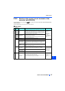
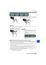
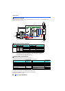
Cable gauge
(mm
2
)
Blade terminal
product number
Insulation
product number
Crimping tool
product number
0.3 to 0.75 BT 0.75-11 VC 0.75 NH 69
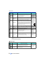
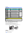
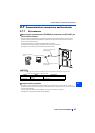
(3) Insert the wires into a socket.
When using a single wire or stranded wires without a blade terminal, push the
open/close button all the way down with a flathead screwdriver, and insert the
wire.
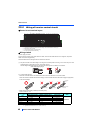
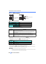
Pull the wire while pushing the open/close button all
the way down firmly with a flathead screwdriver.
Flathead screwdriver
Open/close button
Flathead screwdriver
Open/close button
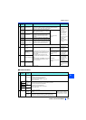
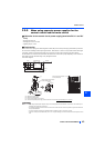
NOTE
• Pulling out the wire forcefully without pushing the open/close
button all the way down may damage the terminal block.
• Use a small flathead screwdriver (tip thickness: 0.4 mm/tip
width: 2.5 mm).
If a flathead screwdriver with a narrow tip is used, terminal
block may be damaged.
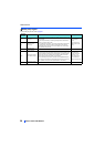
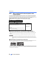
Commercially available products (as of February 2012)
• Place the flathead screwdriver vertical to the open/close
button. In case the blade tip slips, it may cause an inverter
damage or injury.
Name Model Manufacturer
Driver
SZF
0- 0,4 2,5
Phoenix Contact Co., Ltd.
Contact Co., Ltd.