


Connection of motor with encoder (vector control)
50
INSTALLATION AND WIRING
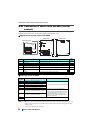
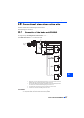
2.8 Connection of motor with encoder (vector
control)
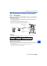
Using an encoder-equipped motor together with the plug-in option FR-A8AP enables speed, torque, and positioning control
operations under orientation control, encoder feedback control, and full-scale vector control.
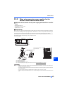
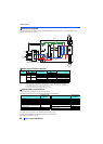
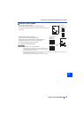
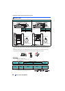
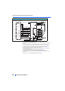
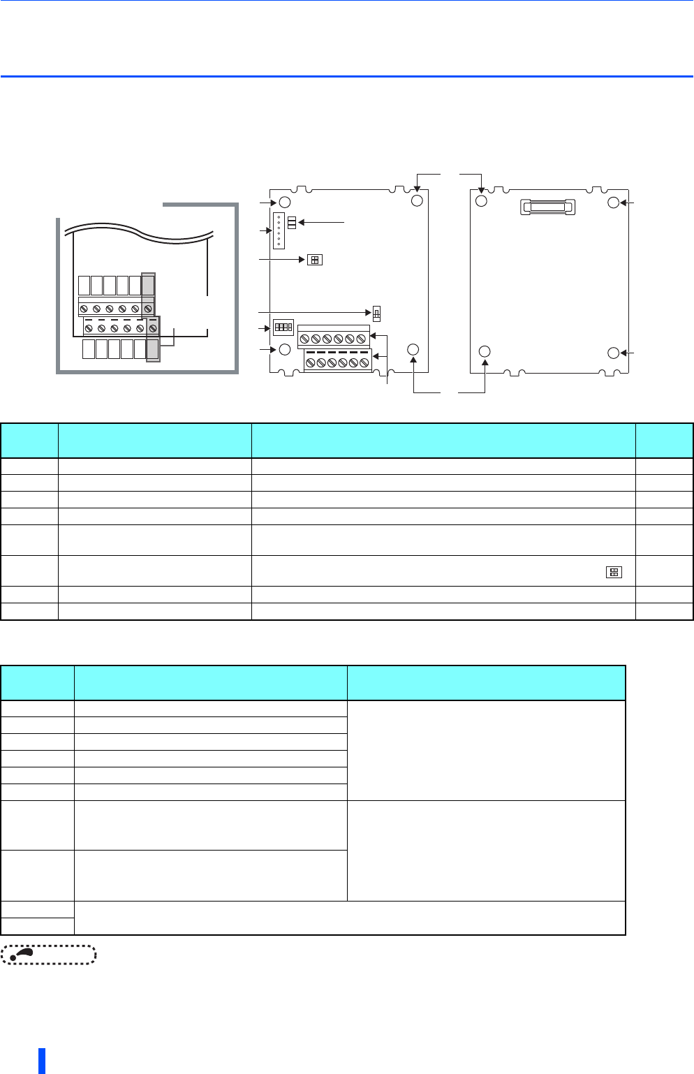
Appearance and parts name of FR-A8AP
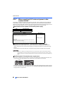
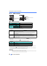
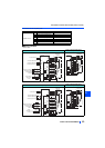
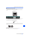
Terminals of the FR-A8AP
NOTE
• When the encoder's output voltage differs from its input power supply voltage, the signal loss detection (E.ECT) may occur.
• Incorrect wiring or faulty setting to the encoder will cause a fault such as an overcurrent (E.OC[ ]) and an inverter
overload (E.THT).
Correctly perform the encoder wiring and setting.
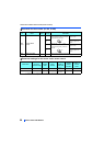
Symbol Name Description
Refer
to page
a Mounting hole Used for installation to the inverter. —
b Terminal block Connected with the encoder. 53
c Encoder type selection switch (SW3) Switches the encoder type (differential line driver/complementary). 51
d CON2 connector Not used. —
e
Terminating resistor selection switch
(SW1)
Switches ON or OFF the internal terminating resistor. 51
f
Switch for manufacturer setting
(SW2)
Do not change from the initially-set status. (Switches 1 and 2 are OFF .)
—
g Connector Connected to the option connector of the inverter. 9
h LED for manufacturer check Not used. —
Terminal
symbol
Terminal name Description
PA1 Encoder A-phase signal input terminal
A-, B- and Z-phase signals are input from the encoder.
PA2 Encoder A-phase inverse signal input terminal
PB1 Encoder B-phase signal input terminal
PB2 Encoder B-phase inverse signal input terminal
PZ1 Encoder Z-phase signal input terminal
PZ2 Encoder Z-phase inverse signal input terminal
PG Encoder power supply (positive side) input terminal
Input terminal for the encoder power supply.
Connect the external power supply (5 V, 12 V, 15 V, 24
V) and the encoder power cable. When the encoder
output is the differential line driver type, only 5 V can
be input. Make the voltage of the external power
supply same as the encoder output voltage. (Check
the encoder specification.)
SD Encoder power supply ground terminal
PIN
Not used.
PO
Front view
Rear view
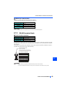
Terminal layout
PA2
PB2
PZ2
SD
SD
PO
PA1
PB1
PZ1
PG
PG
PIN
PIN and PO
are not used.
1
2
3
4
O
N
1
2
O
N
SW2
SW3
SW1
(a)
(a)
(a)
(b)
(a)
(a)
(a)
(e)
(d)
(f)
(c)
(h)
1
2
O
N