


Terminal connection diagrams
24
INSTALLATION AND WIRING
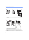
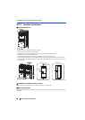
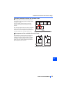
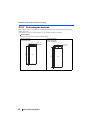
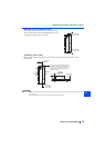
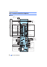
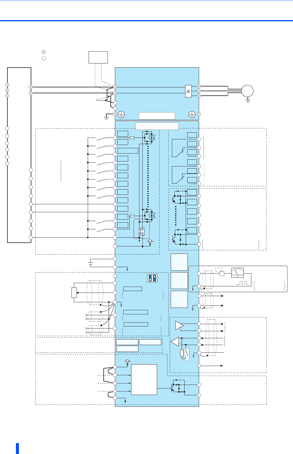
2.4 Terminal connection diagrams
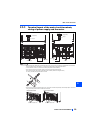
FM type
R1/L11
S1/L21
PC
Frequency setting signals (Analog)
10E(+10V)
10(+5V)
2
(Analog common)
2
3
1
Auxiliary
input
Terminal 4 input
(Current input)
1
4
Frequency setting
potentiometer
1/2W1kΩ
Running
Up to frequency
Overload
Frequency detection
Open collector output common
Sink/source common
F/C
(FM)
SD
Motor
Relay output 1
(Fault output)
C1
B1
A1
U
V
W
Indicator
(Frequency
meter, etc.)
+-
(-)
(+)
Analog signal output
(0 to ±10VDC)
Earth
(Ground)
AM
5
0 to ±5VDC selectable
0 to ±10VDC
Open collector output
Moving-coil type
1mA full-scale
Calibration
resistor
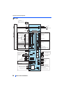
Main circuit terminal
Control circuit terminal
0 to 5VDC
0 to 10VDC
C2
B2
A2
Relay output 2
Relay output
M
0 to 20mADC
0 to 5VDC
0 to 10VDC
selectable
4 to 20mADC
TXD+
TXD-
RXD+
RXD-
SG
Data
transmission
GND
RS-485 terminals
SINK
SOURCE
Connector for plug-in option connection
STF
STR
STP(STOP)
RH
RM
RL
JOG
RT
MRS
X10
RES
AU
CS
SD
RUN
SU
IPF
OL
FU
SE
Data
reception
(+)
(-)
5
VCC
(+)
(-)
5V
Sink logic
Earth (Ground)
N/-
P/+
Initial value
ON
OFF
42
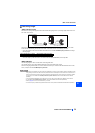
Safety stop signal
Safety monitor output
Safety monitor output common
So
SOC
Safety stop input (Channel 1)
Shorting
wire
Safety stop input common
Safety stop input (Channel 2)
S1
S2
PC
SD
SIC
+24
SD
Brake unit
(Option)
Jumper
(Permissible load
current 100mA)
connector 1 connector 2
connector 3
24V external power
supply input
Common terminal
24VDC power supply
(Common for external power supply transistor)
Forward rotation start
Reverse rotation start
Start self-holding selection
Middle speed
High speed
Low speed
Jog operation
Second function selection
Reset
Terminal 4 input selection
Selection of automatic restart
after instantaneous power failure
Control input signals
(No voltage input allowed)
Multi-speed
selection
Contact input common
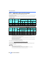
Main circuit
Control circuit
PU
connector
USB A
connector
USB
mini B
connector
Voltage/current
input switch
selectable
Terminating
resistor
Initial value
Initial value
Output stop
RDA
RDI
Converter
unit
RSO
SE
N/-
P/+
IPF
RDB
FAN
R/L1
S/L2
T/L3
OH
RES
SD
PC
+24
C1
B1
A1
24V
24V
Output shutoff
circuit