Communication connectors and terminals
INSTALLATION AND WIRING
49
2
USB device communication
A USB (Ver. 1.1) cable connects the inverter with a personal computer.
Parameter setting and monitoring can be performed by FR Configurator 2.
NOTE
• For the details of FR Configurator2, refer to the Instruction Manual of FR Configurator2.
2.7.3 RS-485 terminal block
Communication operation
The RS-485 terminals enables communication operation from a personal computer, etc. When the PU connector is connected
with a personal, FA or other computer by a communication cable, a user program can run to monitor the inverter or read and
write parameters.
Communication can be performed with the Mitsubishi inverter protocol (computer link operation) and Modbus-RTU protocol.
(For details, refer to the FR-A800 Instruction Manual (Detailed).)
NOTE
• To avoid malfunction, keep the RS-485 terminal wires away from the control circuit board.
• For wiring of the RS-485 terminals used with a plug-in option, lead the wires on the left side of the plug-in option.
Interface
Conforms to USB1.1
Transmission speed
12 Mbps
Wiring length
Maximum 5 m
Connector
USB mini B connector (receptacle)
Power supply
Self-powered
Conforming standard
EIA-485 (RS-485)
Transmission format
Multidrop link
Communication speed
115200 bps maximum
Overall length
500 m
Connection cable
Twisted pair cable (4 pairs)
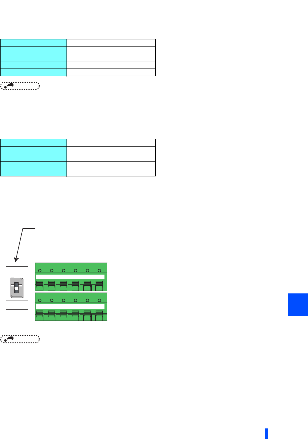
Terminating resistor switch
Initially-set to "OPEN".
Set only the terminating resistor switch of
the remotest inverter to the "100Ω" position.
OPEN
100Ω
+-+
TXD RXD
-
VCC GND
+-+
TXD RXD
-
VCC GND
RDA1
(RXD1+)
RDB1
(RXD1-)
RDA2
(RXD2+)
RDB2
(RXD2-)
SDA1
(TXD1+)
SDB1
(TXD1-)
SDA2
(TXD2+)
SDB2
(TXD2-)
P5S
(VCC)
SG
(GND)
P5S
(VCC)
SG
(GND)


