


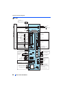
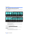
Control circuit
34
INSTALLATION AND WIRING
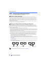
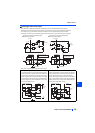
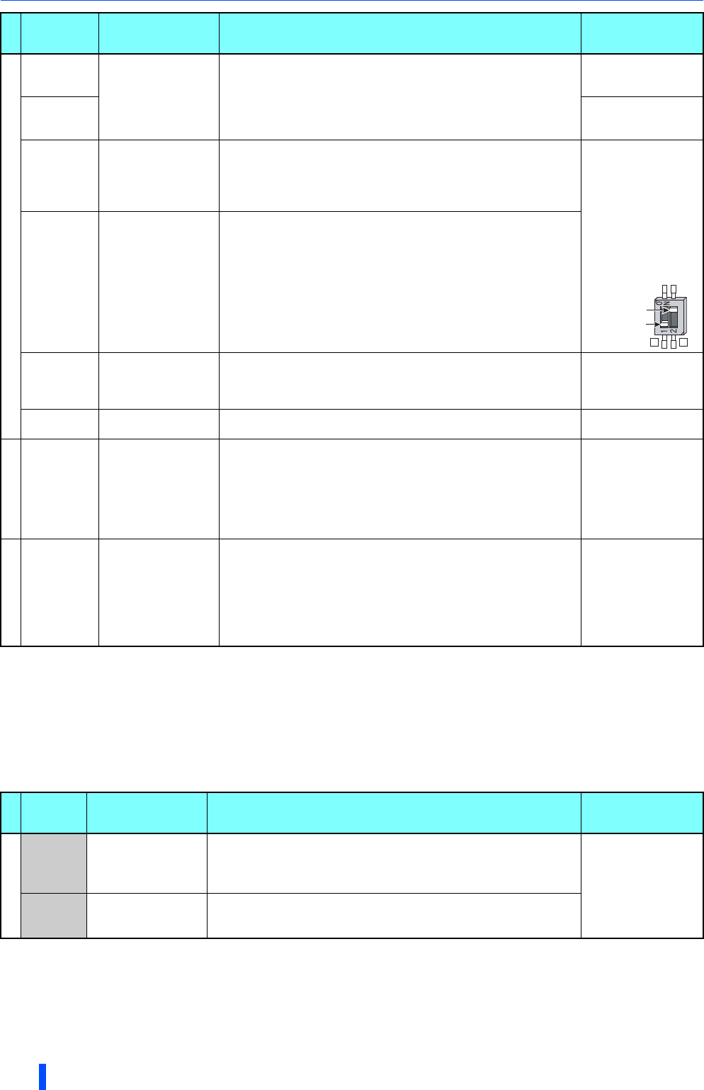
Set Pr.73, Pr.267, and the voltage/current input switch correctly, then input an analog signal in accordance with the setting.
Applying a voltage with the voltage/current input switch ON (current input is selected) or a current with the switch OFF (voltage input is selected)
could cause component damage of the inverter or analog circuits of output devices. (For the details, refer to the FR-A800 Instruction Manual
(Detailed).)
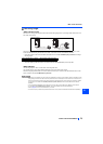
The sink logic is initially set for the FM-type inverter.
The source logic is initially set for the CA-type inverter.
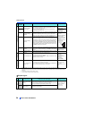
Output signal
Frequency setting
10E
Frequency setting
power supply
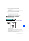
When connecting the frequency setting potentiometer at an initial
status, connect it to the terminal 10.
Change the input specifications of the terminal 2 in Pr.73 when
connecting it to the terminal 10E.
10 VDC 0.4 V
Permissible load
current 10 mA
10
5 VDC0.5 V
Permissible load
current 10 mA
2
Frequency setting
(voltage)
Inputting 0 to 5 VDC (or 0 to 10 V, 0 to 20 mA) provides the maximum
output frequency at 5 V (10 V, 20 mA) and makes input and output
proportional. Use Pr.73 to switch among input 0 to 5 VDC (initial
setting), 0 to 10 VDC, and 0 to 20 mA. Set the voltage/current input
switch in the ON position to select current input (0 to 20 mA).
When voltage is input:
Input resistance 10
k 1 k
Maximum permissible
voltage 20 VDC
When current is input:
Input resistance 245
5
Permissible maximum
current 30 mA
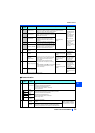
4
Frequency setting
(current)
Inputting 4 to 20 mADC (or 0 to 5 V, 0 to 10 V) provides the maximum
output frequency at 20 mA and makes input and output proportional.
This input signal is valid only when the AU signal is ON (terminal 2
input is invalid). Use Pr.267 to switch among input 4 to 20 mA (initial
setting), 0 to 5 VDC, and 0 to 10 VDC. Set the voltage/current input
switch in the OFF position to select voltage input (0 to 5 V/0 to 10 V).
Use Pr.858 to switch terminal functions.
1
Frequency setting
auxiliary
Inputting 0 to 5 VDC or 0 to 10 VDC adds this signal to terminal 2 or
4 frequency setting signal. Use Pr.73 to switch between input 0 to 5
VDC and 0 to 10 VDC (initial setting). Use Pr.868 to switch terminal
functions.
Input resistance 10
k 1 k
Permissible maximum
voltage 20 VDC
5
Frequency setting
common
Common terminal for frequency setting signal (terminal 2, 1 or 4) and
analog output terminal AM. Do not earth (ground).
———
Thermistor
10
2
PTC thermistor input
For receiving PTC thermistor outputs.
When PTC thermistor is valid (Pr.561 "9999"), the terminal 2 is not
available for frequency setting.
Applicable PTC
thermistor
specification
Overheat detection
resistance:
0.5 to 30 k
(Set by Pr.561)
Power supply input
+24
24 V external power
supply input
For connecting a 24 V external power supply.
If a 24 V external power supply is connected, power is supplied to the
control circuit while the main power circuit is OFF.
Input voltage 23 to
25.5 VDC
Input current 1.4 A or
less
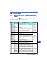
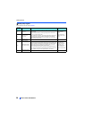
Type
Terminal
Symbol
Terminal name Terminal function description Rate Specification
Relay
A1,
B1,
C1
Relay output 1 (fault
output)
1 changeover contact output that indicates that an inverter's protective
function has been activated and the outputs are stopped.
Fault: discontinuity across B and C (continuity across A and C), Normal:
continuity across Band C (discontinuity across A and C)
Contact capacity 230
VAC 0.3 A (power
factor = 0.4)
30 VDC 0.3 A
A2,
B2,
C2
Relay output 2 1 changeover contact output
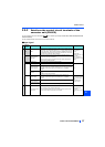
Type
Terminal
Symbol
Terminal name Terminal function description Rate Specification
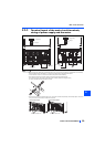
Voltage/current
input switch
2 4
switch1
switch2