


Installation of the inverter and enclosure design
INSTALLATION AND WIRING
23
2
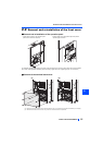
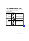
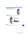
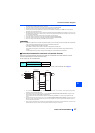
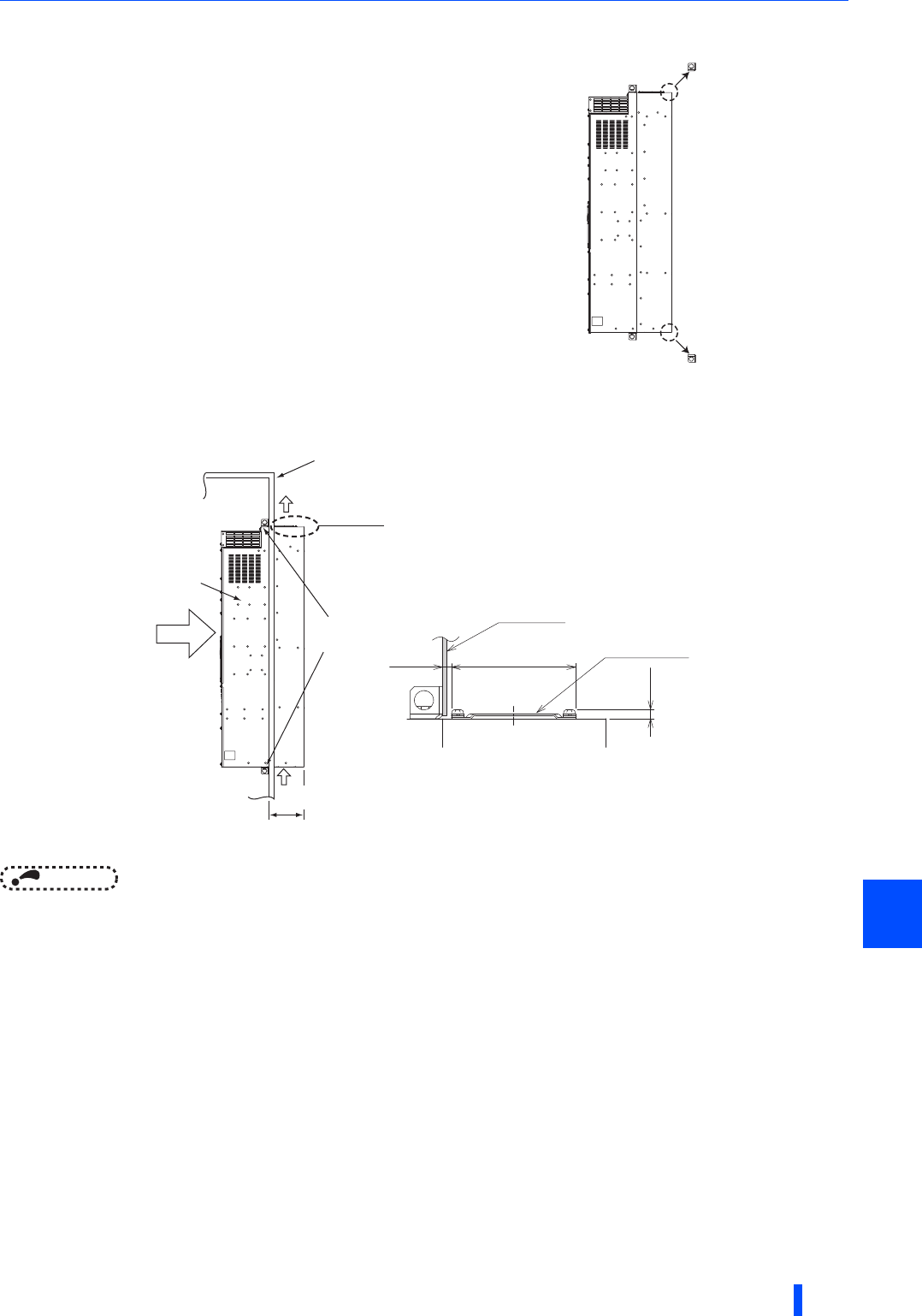
Removal of the rear installation frame
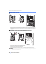
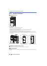
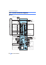
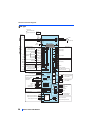
Installation of the inverter
Push the inverter heatsink portion outside the enclosure and fix the enclosure and inverter with upper and lower
installation frame.
NOTE
• Having a cooling fan, the cooling section which comes out of the enclosure cannot be used in the environment of water drops,
oil, mist, dust, etc.
• Be careful not to drop screws, dust etc. into the inverter and cooling fan section.
Two installation frames are attached to each of the upper and lower
parts of the inverter. Remove the rear side installation frame on the top
and bottom of the inverter as shown on the right.
Upper installation
frame (rear side)
Lower installation
frame (rear side)
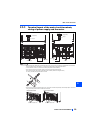
185mm
Exhausted air
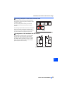
There are finger guards behind the enclosure.
Therefore, the thickness of the panel should be
less than 10 mm (∗1) and also do not place
anything around finger guards to avoid contact
with the finger guards.
140mm
6mm
Inverter
Inside the
enclosure
Enclosure
Installation
frame
Dimension of
the outside of
the enclosure
Cooling
wind
Enclosure
Finger guard
10mm
∗1