


Electro-magnetic interference (EMI) and leakage currents
66
PRECAUTIONS FOR USE OF THE INVERTER
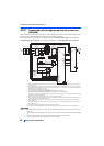
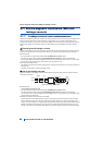
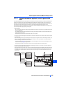
3.1.3 Converter unit (FR-CC2) built-in EMC filter
The converter unit (FR-CC2) is equipped with a built-in EMC filter (capacitive filter).
These filters are effective in reducing air-propagated noise on the input side of the converter unit.
To enable the EMC filter, fit the EMC filter ON/OFF connector to the ON position. The EMC filter is initially set to the "disabled"
(OFF) position.
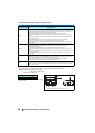
(For the FR-CC2-H400K or higher, two EMC filter ON/OFF connectors are provided. The both connectors are initially set to
the "disabled" (OFF) position. To enable the EMC filter, fit the both EMC filter ON/OFF connectors to the ON position.)
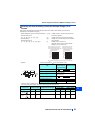
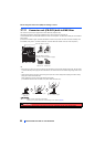
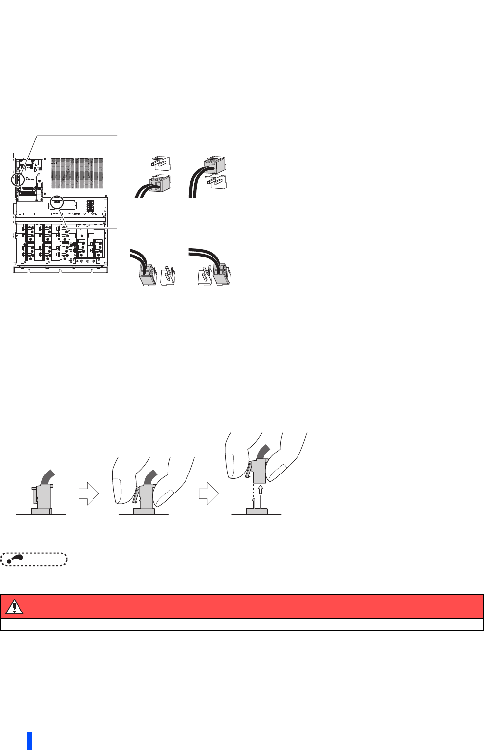
<How to enable or disable the filter>
• Before removing a front cover, check to make sure that the indication of the inverter operation panel is OFF, wait for at least
10 minutes after the power supply has been switched OFF, and check that there is no residual voltage using a tester or the
like.
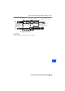
• When disconnecting the connector, push the fixing tab and pull the connector straight without pulling the cable or forcibly
pulling the connector with the tab fixed.
When installing the connector, also engage the fixing tab securely.
(If it is difficult to disconnect the connector, use a pair of needle-nose pliers, etc.)
NOTE
• Fit the connector to either ON or OFF position.
• Enabling (turning ON) the EMC filter increases leakage current. (Refer to page 61.)
Warning
While the inverter power is ON, do not open the front cover. Otherwise you may get an electric shock.
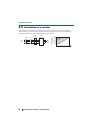
EMC filter OFF EMC filter ON
FILTER
OFF ON
FILTER
OFF ON
FILTER
OFF ON
FILTER
OFF ON
EMC filter ON/OFF connector
EMC filter ON/OFF connector
(Provided for the FR-CC2-H400K or higher)
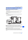
EMC filter OFF EMC filter ON
EMC filter
ON/OFF connector
(Side view)
Disengage connector fixing tab With tab disengaged,
pull up the connector straight.