


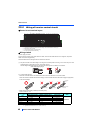
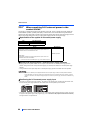
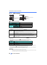
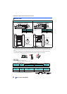
Communication connectors and terminals
48
INSTALLATION AND WIRING
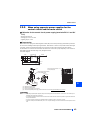
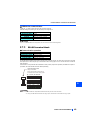
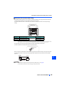
2.7.2 USB connector
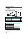
USB host communication
• Different inverter data can be saved in a USB memory device.
The USB host communication enables the following functions.
• When the inverter recognizes the USB memory device without any problem, is briefly displayed on the
operation panel.
• When the USB memory device is removed, is briefly displayed on the operation panel.
• The operating status of the USB host can be checked on the LED display of the inverter.
• When a device such as a USB battery charger is connected to the USB connector and an excessive current (500 mA or
more) flows, USB host error (UF warning) is displayed on the operation panel.
• If a UF warning occurs, disconnect the USB device and set Pr.1049 = "1" to cancel the USB error. (The UF warning can
also be canceled by resetting the inverter power or resetting with the RES signal.)
NOTE
• Do not connect devices other than a USB memory device to the inverter.
• If a USB device is connected to the inverter via a USB hub, the inverter cannot recognize the USB memory device properly.
• For the details of usage, refer to the FR-A800 Instruction Manual (Detailed).
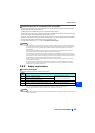
Interface
Conforms to USB1.1
Transmission speed
12 Mbps
Wiring length
Maximum 5 m
Connector
USB A connector (receptacle)
Compatible
USB memory
(Format)
FAT32
Capacity
1 GB or more (used in the recorder mode of the trace function)
Encryption function
Not available
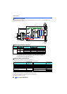
Function Description
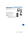
Parameter copy
• Copies the parameter setting from the inverter to the USB memory device. A maximum of 99 parameter setting
files can be saved in a USB memory device.
• The parameter setting data copied in the USB memory device can be copied to other inverters. This function is
useful in backing up the parameter setting or for sharing the parameter setting among multiple inverters.
• The parameter setting data copied in the USB memory device can be saved in a personal computer and edited
in FR Configurator 2.
Trace
• The monitored data and output status of the signals can be saved in a USB memory device.
• The saved data can be imported to FR Configurator2 to diagnose the operating status of the inverter.
PLC function data
copy
• This function copies the PLC function project data to a USB memory device when the PLC function is used.
• The PLC function project data copied in the USB memory device can be copied to other inverters.
• This function is useful in backing up the parameter setting and for allowing multiple inverters to operate by the
same sequence programs.
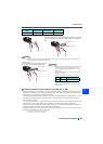
LED display
status
Operating status
OFF No USB connection.
ON The communication is established between the inverter and the USB device.
Flickering rapidly The USB memory device is being accessed. (Do not remove the USB memory device.)
Flickering slowly Error in the USB connection.
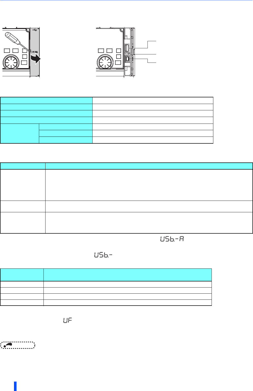
USB host
(A connector)
USB device
(Mini B connector)
Communication status indicator (LED)
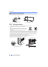
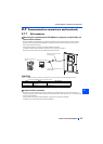
Place a flathead screwdriver,
etc. in a slot and push up the
cover to open.