


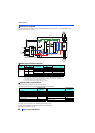

Control circuit
42
INSTALLATION AND WIRING
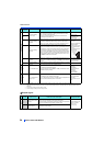
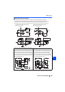
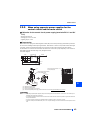
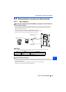
Signal inputs by contactless switches
The contact input terminals of the inverter (STF, STR, STOP, RH, RM, RL, JOG, RT, MRS, RES, AU, CS) can be controlled
using a transistor instead of a contact switch as shown below.
2.6.5 Wiring precautions
• It is recommended to use a cable of 0.75 mm
2
for the connection to the control circuit terminals.
• The wiring length should be 30 m (200 m for the terminal FM) at the
maximum.
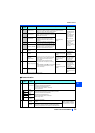
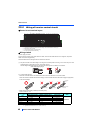
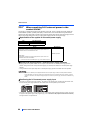
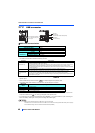
• Use two or more parallel micro-signal contacts or twin contacts to prevent
contact faults when using contact inputs since the control circuit input signals
are micro-currents.
• To suppress EMI, use shielded or twisted cables for the control circuit
terminals and run them away from the main and power circuits (including the 200V relay sequence circuit). For the cables
connected to the control circuit terminals, connect their shields to the common terminal of the connected control circuit
terminal. When connecting an external power supply to the terminal PC, however, connect the shield of the power supply
cable to the negative side of the external power supply. Do not directly earth (ground) the shield to the enclosure, etc.
• Do not apply a voltage to the contact input terminals (STF, etc.) of the control circuit.
• Always apply a voltage to the fault output terminals (A1, B1, C1, A2, B2, C2) via a relay coil, lamp, etc.
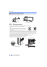
• Separate the wiring of the control circuit away from the wiring of the main circuit.
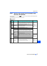
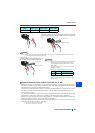
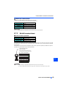
Make cuts in rubber bush of the inverter side and lead the wires through.
+24V
STF, etc
SD
Inverter
External signal input using transistor
(sink logic)
PC
R
STF, etc
+24V
Inverter
External signal input using transistor
(source logic)
Micro signal contacts Twin contacts
Rubber bush
(viewed from inside)
Make cuts along the lines on
the inside with a cutter knife
<Wiring example>