


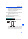
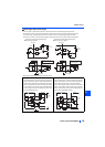
Control circuit
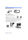
INSTALLATION AND WIRING
35
2
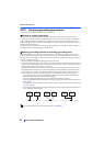
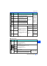
Terminal FM is provided in the FM-type inverter.
Terminal CA is provided in the CA-type inverter.
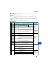
Communication
Open collector
RUN Inverter running
Switched to LOW when the inverter output frequency is equal to or
higher than the starting frequency (initial value 0.5 Hz). Switched to
HIGH during stop or DC injection brake operation.
Permissible load 24
VDC (maximum 27
VDC) 0.1 A
(The voltage drop is
2.8 V at maximum
while the signal is
ON.)
LOW is when the
open collector output
transistor is ON
(conducted).
HIGH is when the
transistor is OFF (not
conducted).
SU Up to frequency
Switched to LOW when the output frequency
is within the set frequency range 10% (initial
value). Switched to HIGH during acceleration/
deceleration and at a stop.
Fault code (4 bits)
output.
OL Overload alarm
Switched to LOW when stall prevention is
activated by the stall prevention function.
Switched to HIGH when stall prevention is
canceled.
IPF Open collector output
No function is assigned in the initial setting.
The function can be assigned setting Pr.192.
FU Frequency detection
Switched to LOW when the inverter output
frequency is equal to or higher than the preset
detection frequency, and to HIGH when it is
less than the preset detection frequency.
SE
Open collector output
common
Common terminal for terminals RUN, SU, OL, IPF, FU ———
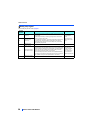
Pulse
FM
For meter
Outputs a selected monitored item (such as
output frequency) among several monitored
items. The signal is not output during an
inverter reset.
The output signal is proportional to the
magnitude of the corresponding monitoring
item.
Use Pr.55, Pr.56, and Pr.866 to set full scales
for the monitored output frequency, output
current, and torque.
Output item:
Output frequency (initial
setting)
Permissible load
current 2 mA
For full scale
1440 pulses/s
NPN open
collector output
This terminal can be
used for open collector
outputs by setting
Pr.291.
Maximum output
pulse: 50k pulses/s
Permissible load
current: 80 mA
Analog
AM Analog voltage output
Output item:
Output frequency (initial
setting)
Output signal 0 to 10
VDC, Permissible
load current 1 mA
(load impedance 10
k or more)
resolution 8 bits
CA
Analog current output
Load impedance 200
to 450
Output signal 0 to 20
mADC
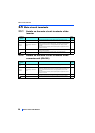
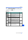
Type
Terminal
symbol
Terminal
name
Terminal function description
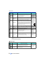
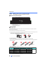
RS-485
— PU connector
With the PU connector, communication can be made through RS-485. (For connection on a 1:1 basis
only)
Conforming standard: EIA-485 (RS-485)
Transmission format: Multidrop link
Communication speed: 4800 to 115200 bps
Wiring length: 500 m
RS-485 terminals
TXD+
Inverter
transmission
terminal
The RS-485 terminals enable the communication by RS-485.
Conforming standard: EIA-485 (RS-485)
Transmission format: Multidrop link
Communication speed: 300 to 115200 bps
Overall length: 500 m
TXD-
RXD+
Inverter
reception
terminal
RXD-
SG
Earthing
(grounding)
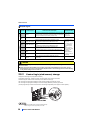
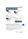
USB
—
USB A
connector
A connector (receptacle)
A USB memory device enables parameter copies and the trace
function.
Interface: Conforms to USB1.1
(USB2.0 fullspeed compatible)
Transmission speed: 12 Mbps
USB B
connector
Mini B connector (receptacle)
Connected to a personal computer via USB to enable setting,
monitoring, test operations of the inverter by FR Configurator2.
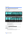
Type
Terminal
Symbol
Terminal name Terminal function description Rate Specification