


Inverter rating
98
SPECIFICATIONS
6.1 Inverter rating
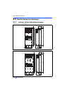
400 V class
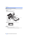
• Inverter
The applicable motor capacity indicated is the maximum capacity applicable for use of the Mitsubishi 4-pole standard motor.
The rated output capacity indicated assumes that the output voltage is 440 V.
The % value of the overload current rating indicated is the ratio of the overload current to the inverter's rated output current. For repeated duty,
allow time for the inverter and motor to return to or below the temperatures under 100% load.
The maximum output voltage does not exceed the power supply voltage. The maximum output voltage can be changed within the setting range.
However, the maximum point of the voltage waveform at the inverter output side is the power supply voltage multiplied by about .
ND rating reference value
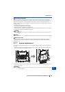
FR-DU08: IP40 (except for the PU connector section)
For the power voltage exceeding 480 V, set Pr.977 Input voltage mode selection. (For details, refer to the FR-A800 Instruction Manual
(Detailed).)
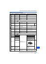
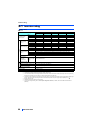
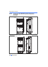
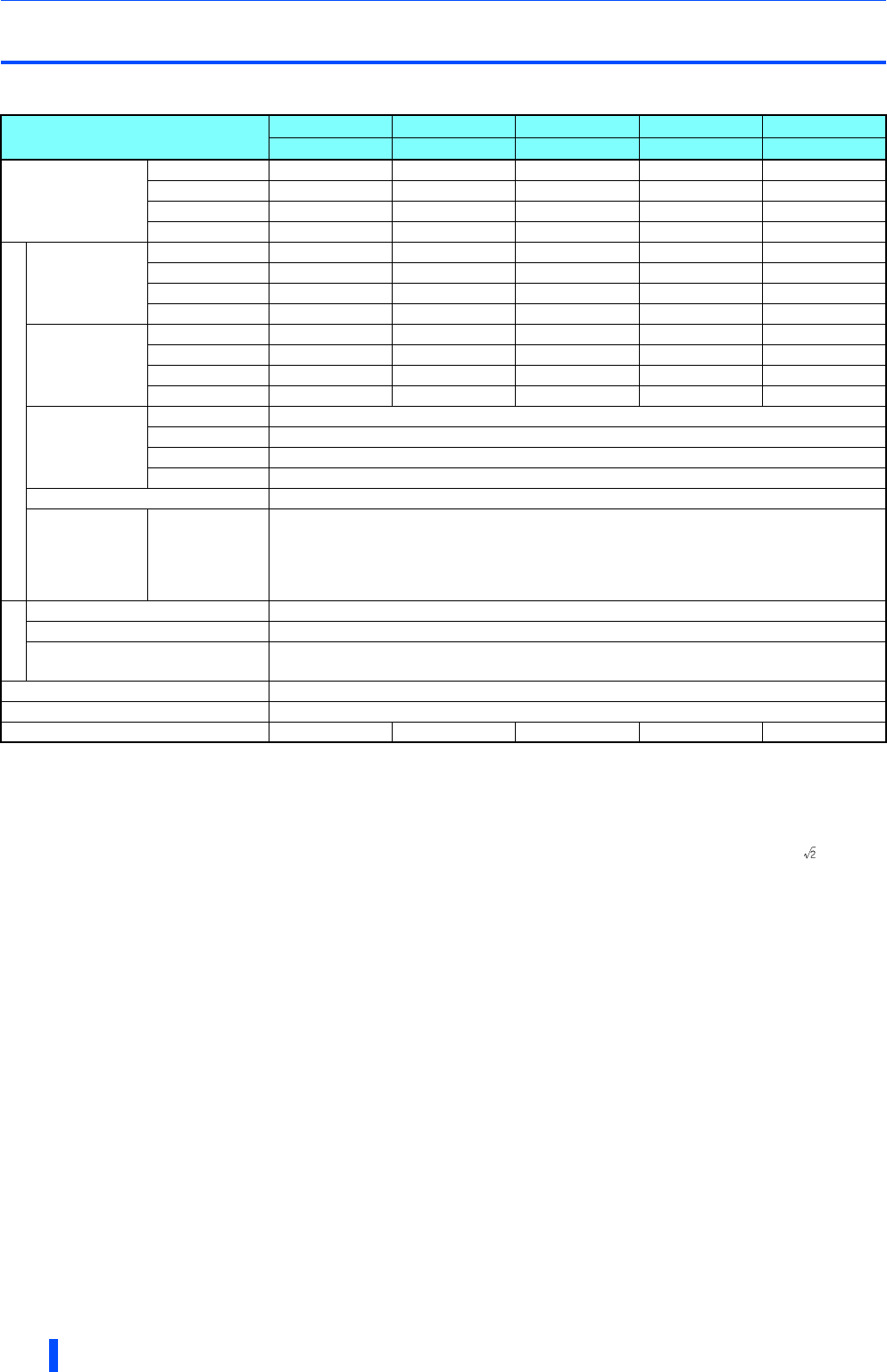
Model FR-A842-[ ]
315K 355K 400K 450K 500K
07700 08660 09620 10940 12120
Applicable motor
capacity (kW)
SLD 400 450 500 — —
LD 355 400 450 500 —
ND (initial setting) 315 355 400 450 500
HD 280 315 355 400 450
Output
Rated capacity
(kVA)
SLD 587 660 733 834 924
LD 521 587 660 733 834
ND (initial setting) 465 521 587 660 733
HD 417 465 521 587 660
Rated current (A)
SLD 770 866 962 1094 1212
LD 683 770 866 962 1094
ND (initial setting) 610 683 770 866 962
HD 547 610 683 770 866
Overload current
rating
SLD 110% 60 s, 120% 3 s (inverse-time characteristics) at surrounding air temperature 40°C
LD 120% 60 s, 150% 3 s (inverse-time characteristics) at surrounding air temperature 50°C
ND (initial setting) 150% 60 s, 200% 3 s (inverse-time characteristics) at surrounding air temperature 50°C
HD 200% 60 s, 250% 3 s (inverse-time characteristics) at surrounding air temperature 50°C
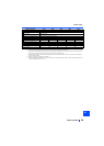
Rated voltage
Three-phase 380 to 500 V
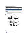
Regenerative
brakingtorque
(When the
converter unit
(FR-CC2) is used)
Maximum brake
torque
10% torque/continuous
Input power
DC power supply voltage 430 to 780 VDC
Control power supply auxiliary input Single phase 380 to 500 V 50 Hz/60 Hz
Permissible control power supply
auxiliary input fluctuation
Frequency 5%, voltage 10%
Protective structure (IEC 60529)
Open type (IP00)
Cooling system Forced air cooling
Approx. mass (kg) 163 163 243 243 243