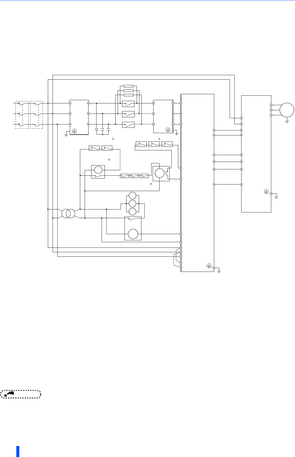
Connection of stand-alone option units
58
INSTALLATION AND WIRING
2.9.2 Connection of the high power factor converter
(FR-HC2)
When connecting the high power factor converter (FR-HC2) to suppress power harmonics, perform wiring securely as shown
below. Incorrect connection will damage the high power factor converter and the inverter.
After making sure that the wiring is correct, set "rated motor voltage" in Pr.19 Rated motor voltage (under V/F control) or
Pr.83 Regenerative function selection (under other that V/F control) and "2" in Pr.30 Regenerative function selection.
NOTE
• The voltage phases of terminals R/L1, S/L2, and T/L3 and the voltage phases of terminals R4/L14, S4/L24, and T4/L34 must
be matched.
• The control logic (sink logic/source logic) of the high power factor converter and the inverter must be matched. (Refer to page
38.)
• When using a sine wave filter with FR-HC2, select MT-BSL-HC as a reactor for the sine wave filter.
• For the parameter details, refer to the FR-A800 Instruction Manual (Detailed).
Remove jumpers installed in terminals R1/L11 and S1/L21 of the inverter, and connect the power supply for the control circuit to terminals
R1/L11 and S1/L21.
The voltage phases of terminals R4/L14, S4/L24, and T4/L34 and the voltage phases of terminals R/L1, S/L2, and T/L3 must be matched.
Do not install an MCCB across the terminals P/+ and N/- (across terminals P and P/+ or across N and N/-). Connecting the opposite polarity
of terminals N/- and P/+ will damage the inverter.
For the A802 series, installation of a fuse is not required.
Change the FR-HC2 parameter setting to Pr.10 RDY signal logic selection = "0" (positive logic).
Use Pr.178 to Pr.189 (input terminal function selection) to assign the terminals used for the X10 signal.
For RS-485 or any other communication where the start command is only transmitted once, use the X11 signal to save the operation mode
at the time of an instantaneous power failure.
Assign the IPF signal to an FR-HC2 terminal. (Refer to the Instruction Manual of FR-HC2.)
Always connect the FR-HC2 terminal RDY to the inverter terminal MRS(X10), and the FR-HC2 terminal SE to the inverter terminal SD. Not
connecting these terminals may damage the FR-HC2.
Always connect the R/L1, S/L2, and T/L3 terminals of FR-HC2 to the power supply. Operating the inverter without connecting them will
damage the FR-HC2.
Do not install an MCCB or MC between the reactor 1 terminals (R/L1, S/L2, T/L3) and the FR-HC2 terminals (R4/L14, S4/L24, T4/L34). It
will not operate properly.
Securely perform grounding (earthing) by using the grounding (earthing) terminal.
The number of connected peripheral devices differs according to the capacity. For the detail, refer to the FR-HC2 Instruction Manual.
MC1
MC2
MC3
M
R1/L11
S1/L21
R4/L14
S4/L24
T4/L34
R4/
L14
S4/
L24
T4/
L34
R3/
L13
S3/
L23
T3/
L33
R2/
L12
S2/
L22
T2/
L32
R/
L1
S/
L2
T/
L3
MC
U
V
W
88R
R/L1
S/L2
T/L3
88S
R1/L11
S1/L21
MC
Bu1
MC1
MC2
MC3
ROH
SD
MC2
MC3
MC
Small
MC
Bu2
MC1
P/+P/+
N/-
N/-
X11
RES
SD
IPF
RSO
SE
∗11
∗11
∗11
∗9 ∗9 ∗9
∗10
∗5
∗4
∗6
X10
RDY
∗7
∗7
∗1
∗10
∗8
∗3
∗2
Inverter
High power
factor converter
(FR-HC2)
Limit resistor
Reactor 1
(FR-HCL21)
Power
Supply
MCCB
Reactor 2
(FR-HCL22)
Earth
(Ground)
Limit MC
Buffer relay for driving MCs
MC power
supply
stepdown
transformer
Mini relay for filter
capacitor alarm detector
Buffer relay for
filter capacitor
alarm detectors
Auxiliary contact for
limit MCs (NO contact) 3
Filter capacitor
alarm detector
(NC contact) 2
Limit resistor (with thermostat)
(NC contact) 3
Filter capacitors 2
(FR-HCC2)


