


TABLE OF CONTENTS Teledyne API - T100H Addendum to T100 Operation Manual
x
10.3.2. Sensor Module Repair & Cleaning...........................................................................................47
10.3.2.1. Adjusting the UV Lamp (Peaking the Lamp) .........................................................................48
10.3.2.2. PMT Hardware Calibration (FACTORY CAL) ........................................................................50
10.4. Technical Assistance ................................................................................................................52
LIST OF FIGURES
Figure 3-1: Example of Pneumatic Connections to T100H External Pump .......................................... 17
Figure 3-2: Pneumatic Connections to T100H with Zero and Two Span Point Valve Option ..................... 18
Figure 3-3: Internal Pneumatic flow for T100H in Basic Configuration............................................... 19
Figure 3-4: T100H Layout (Basic Unit – No Valve Options)............................................................ 20
Figure 5-1: Pneumatic Diagram of the T100H With Z/S Option Installed............................................. 25
Figure 5-2: Pneumatic Diagram of the T100H with Option 50C Installed ............................................ 26
Figure 5-3: Hydrocarbon Scrubber (Kicker) – OPT 86D ................................................................ 27
Figure 5-4: T100H Internal Pneumatic Diagram with Hydrocarbon Scrubber Installed ............................ 28
Figure 6-1: Control Input Connector ....................................................................................... 32
Figure 9-1: UV Light Path ................................................................................................... 39
Figure 9-2: Pneumatic Diagram of the T100H – Base Configuration ................................................. 41
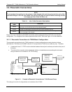
Figure 9-3: T100H Electronic Block Diagram ............................................................................ 43
Figure 9-4: T100H Power Distribution Block Diagram .................................................................. 44
Figure 10-1: Flow Control Assembly ........................................................................................ 46
Figure 10-2: Sensor Module Wiring and Pneumatic Fittings............................................................. 47
Figure 10-3: Shutter Assembly - Exploded View .......................................................................... 48
Figure 10-4: Location of UV Reference Detector Potentiometer........................................................ 49
Figure 10-5: Pre-Amplifier Board Layout ................................................................................... 50
LIST OF TABLES
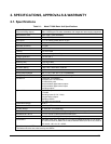
Table 2-1: Model T100H Basic Unit Specifications...................................................................... 13
Table 3-1: Inlet / Outlet Connector Descriptions ......................................................................... 17
Table 2-1: Possible Warning Messages at Start-Up .................................................................... 21
Table 5-1: Two-Point Span Valve Operating States..................................................................... 27
Table 6-1: Additional T100H Warning Messages........................................................................ 29
Table 6-2: Additional T100H Test Functions ............................................................................. 29
Table 6-3: Additional T100H Test Parameters Available for Analog Output A3..................................... 29
Table 6-4: T100H Default Hessen Status Bit Assignments ............................................................ 30
Table 6-5: Status Output Signals .......................................................................................... 31
Table 6-6: Control Input Signals ........................................................................................... 32
Table 8-1: Predictive Uses for Test Functions ........................................................................... 37
Table 10-1: Warning Messages - Indicated Failures ..................................................................... 45
Table 10-2: Test Functions - Possible Causes for Out-Of-Range Values ............................................. 45
Table 10-3: Example of HVPS Power Supply Outputs ................................................................... 49
LIST OF APPENDICES
APPENDIX A – MENU TREES AND SOFTWARE DOCUMENTATION
APPENDIX B - PARE PARTS LIST
APPENDIX C - REPAIR QUESTIONNAIRE
07265A DCN6038