


TROUBLESHOOTING & REPAIR Teledyne API - T100H Addendum to T100 Operation Manual)
46
10.3. Repair Procedures
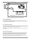
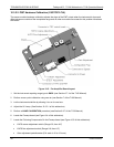
10.3.1. Repairing the Sample Gas Flow Control Assembly
The Critical Flow Orifice is part of the pressure sensor and flow control assembly. The jewel orifice is protected
by a sintered filter, so it is unusual for the orifice to need replacing, but it is possible for the sintered filter and o-
rings to need replacing. See the Spare Parts list in Appendix B for part numbers and kits.
To replace the filter and/or orifice
1. Turn off Power to the analyzer.
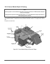
2. Locate the pressure sensor / flow control assembly.
3. Disconnect the signal cable and pneumatic fittings.
4. Remove the assembly from the optical bench by removing the 2 screws at each end of the assembly.
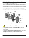
5. The inlet end of the assembly is located at the end with the straight pneumatic fitting. Remove the fitting and
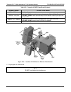
the components as shown in the exploded view.
6. Replace the o-rings (p/n:OR01) and the sintered filter (p/n:FL01).
7. if you are replacing the Critical Flow Orifice itself (p/n:00094100), make sure that the side with the colored
window (usually RED) is facing upstream to the flow gas flow.
8. Re-assemble in reverse order. See the Spares List in Appendix B for part numbers.
9. After re-connecting the power and pneumatic lines, flow check the instrument as described in the Section
1.5.2 of the T100 Operator’s Manual.
Figure 10-1: Flow Control Assembly
07265A DCN6038