


Teledyne API - T100H Addendum to T100 Operation Manual Theory Of Operation
41
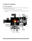
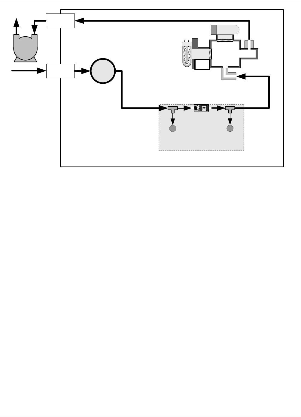
FLOW CONTROL &
PRESSURE SENSOR
VACUUM
PRESSURE
SENSOR
SAMPLE
PRESSURE
SENSOR
CRITICAL
FLOW ORIFICE
700 cm
3
/min
@ 7 In-Hg-A
Particulate
Filter
PUMP
EXHAUST
GAS OUTLET
SAMPLE
GAS INLET
INSTRUMENT CHASSIS
UV
LAMP
PMT
REACTION
CELL
UV
Detector
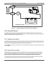
Figure 9-2: Pneumatic Diagram of the T100H – Base Configuration
9.2.2. Pneumatic Sensors
The T100H uses two pneumatic sensors to verify gas flow. These sensors are located on a printed circuit
assembly, called the pneumatic pressure/flow sensor board. This PCA is attached to a manifold containing the
critical flow orifice that sets the instrument flow rate.
9.2.2.1. Sample Pressure Sensor
An absolute pressure transducer plumbed to the input of the analyzer’s sample chamber is used to measure the
pressure of the sample gas before it passes through the critical flow orifice. This is used to validate the critical
flow condition (2:1 pressure ratio) through the instrument’s critical flow orifice.
The actual sample gas pressure measurement is viewable through the analyzer’s front panel display as the test
function PRES
9.2.2.2. Vacuum Pressure Sensor
An absolute pressure transducer measures the pressure on the vacuum side of the critical flow orifice and is
used to measure the sample gas pressure in the reaction cell. If the vacuum pressure is not in the correct
range, a warning will be displayed by the software. Also, if the temperature/pressure compensation (TPC)
feature is turned on, the output of this sensor is also used to supply pressure data for that calculation.
The actual pressure of the gas downstream from the critical flow orifice (including the gas inside the reaction
cell) viewable through the analyzer’s front panel display as the test function VAC
07265A DCN6038