


45
10. TROUBLESHOOTING & REPAIR
For the most part the information contained in Section 11 of the T100 Manual (P/N 06807) is also applicable to
the T100H. There are a few exceptions however.
10.1.1. Fault Diagnosis with Warning Messages
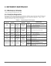
Table 10-1: Warning Messages - Indicated Failures
WARNING
MESSAGE
FAULT CONDITION POSSIBLE CAUSES
VACUUM
PRESS
WARN
Gas pressure inside the
reaction cell outside of
warning limits.
If sample pressure is > 10 in-Hg:
o Pneumatic Leak
o Bad Pump Rebuild Pump
o Failed pressure sensor/circuitry
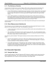
10.1.2. Fault Diagnosis with Test Functions
Table 10-2: Test Functions - Possible Causes for Out-Of-Range Values
TEST
FUNCTION
NOMINAL
VALUE(S)
POSSIBLE CAUSE(S)
VAC
<9.1 IN-HG-A
Incorrect sample gas pressure could be due to: pneumatic leak; malfunctioning valve;
malfunctioning pump; clogged flow orifices; sample inlet overpressure; faulty pressure
sensor
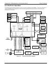
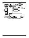
10.2. Subsystem Checkout
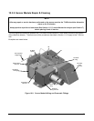
10.2.1. Pneumatic Sensor Assembly
The pneumatic sensor assembly of the T100H differs from that of the T100 in that there is no flow sensor.
Instead the assembly includes two pressure sensors located on either side of a critical flow orifice. The T100H
software infers the gas flow rate by mathematically comparing the two pressure readings.
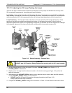
If you suspect that one of the two pressure sensors is failing:
1. Cap the sample inlet.
2. After a few seconds, check the VAC and PRES test functions and verify that:
The VAC value matches the PRES value to within 1 In-Hg-A, and;
Both are less than 10 in-Hg-A (i.e. under vacuum).
3. Uncap the sample inlet and unplug the pump.
4. After a few minutes, the value VAC and PRES should match within 1 In-Hg-A, and read atmospheric
pressure.
If the two sensors do not match or are significantly different from ambient atmospheric pressure, call
Teledyne Instruments customer service.
07265A DCN6038