


Teledyne API - T100H Addendum to T100 Operation Manual TROUBLESHOOTING & REPAIR
51
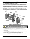
8. Set the HVPS coarse adjustment to its minimum setting (0).
9. Set the HVPS fine adjustment switch to its maximum setting (F).
10. Turn the gain adjustment potentiometer clockwise to its maximum setting.
11. Set the front panel display to show STABIL (see Section 6.2.1 of the T100 Manual)
12. Feed span gas into the analyzer.
13. Wait until the STABIL value is below 0.5 ppm,
NOTE
Use a span gas equal to 80% of the reporting range.
Example: for a reporting range of 200 ppm, use a span gas of 160 ppm.
14. Scroll to the OFFSET function and record the value.
15. Scroll to the NORM PMT value.
NOTE
Do not overload the PMT by accidentally setting both adjustment switches to their maximum setting.
This can cause permanent damage to the PMT.
16. Determine the target NORM PMT value according to the following formulas.
If the reporting range is set for 500 ppm (the instrument will be using the 500 ppm physical range):
Target NORM PMT = (8 x span gas concentration) + OFFSET
If the reporting range is set for 5,001 PPB (the instrument will be using the 5,500 ppm physical range):
Target NORM PMT = (0.8 x span gas concentration) + OFFSET
EXAMPLE: If the OFFSET is 33 mV, the Reporting Range is 1000 ppm, the span gas should be 800
ppm SO
2
and the calculation would be:
Target NORM PMT = (0.8 x 800) + 33 mV
Target NORM PMT =
640 + 33 mV
Target NORM PMT =
673 mV
17. Set the HVPS coarse adjustment switch to the lowest setting that will give you more than the
target NORM PMT signal from Step 16.
The coarse adjustment typically increments the NORM PMT signal in 100-300 mV steps.
18. Adjust the HVPS fine adjustment such that the NORM PMT value is at or just above the target NORM PMT
signal from Step 16.
19. Continue adjusting the both the coarse and fine switches until NORM PMT is as close to (but not below) the
target NORM PMT value from Step 16.
07265A DCN6038