


Teledyne API - T100H Addendum to T100 Operation Manual Theory Of Operation
43
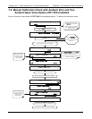
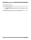
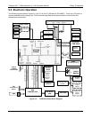
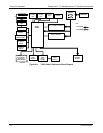
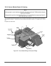
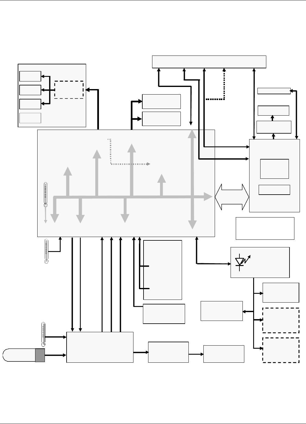
9.3. Electronic Operation
The following figures replace Figures 10-10 & 10-19 of the T100 Manual (P/N 06807). There is no IZS option, a
vacuum pressure sensor replaces the T100’s thermal-mass flow sensor and provision is made for the two
ambient span valve option.
Pneumatic
Sensor
Board
Sample Gas
Pressure
Sensor
Vacuum
Pressure
Sensor
Analog Outputs
Status Outputs:
1 – 8
Control Inputs:
1 – 6
PC 104
CPU Card
Disk On
Module
Flash Chip
Power-Up
Circuit
I
2
C Bus
Analog
Sensor Inputs
Box
Temp
Thermistor
Interface
SAMPLE
CHAMBER
TEMPERATURE
PMT
Temperature
Sensor
A1
A
2
A3
Optional
4-20 mA
MOTHER
BOARD
A/D
Converter
(V/F)
PC 104
Bus
External
Digital I/O)
Analog
Outputs
(D/A)
RELAY
BOARD
I
2
C Status LED
PUMP
(Externally Powered)
A4
Shutter
control
Sample Cal
Valve
Option
2 Span Pt.
Valve
Option
Reaction Cell
Heater
PMT TEC
PMT
TEC Drive
PCA
Internal
Digital I/O
ELECTRIC TEST CONTROL
OPTIC TEST CONTROL
PMT OUTPUT (PMT DET)
HIGH VOLTAGE POWER SUPPLY LEVEL
PMT TEMPERATURE
PMT
PREAMP PCA
UV Reference
Detector
COM1 (RS–232 ONLY)
COM2 (RS
–
232 or RS
–
485)
Display
Touchscreen
LVDS
transmitter board
Analog RS232 COM2 USB Ethernet
IN
Male Female COM port
USB
or USB
(I
2
C Bus)
CPU
Status
LED
Figure 9-3: T100H Electronic Block Diagram
07265A DCN6038