


Teledyne API - T100H Addendum to T100 Operation Manual TROUBLESHOOTING & REPAIR
49
Table 10-3: Example of HVPS Power Supply Outputs
UVLAMP_SIGNAL ACTION TO BE TAKEN
3500mV±200mV. No Action Required
> 4900mV at any time.
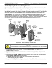
Adjust the UV reference detector potentiometer (see Figure 10-4) until
UVLAMP_SIGNAL reads approximately 3600mV before continuing to adjust the
lamp position.
>4500mV or < 1000mV
Adjust the UV reference detector potentiometer (see Figure 10-4) until
UVLAMP_SIGNAL reads as close to 3500mV as possible.
.< 600mV Replace the lamp.
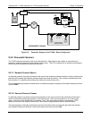
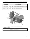
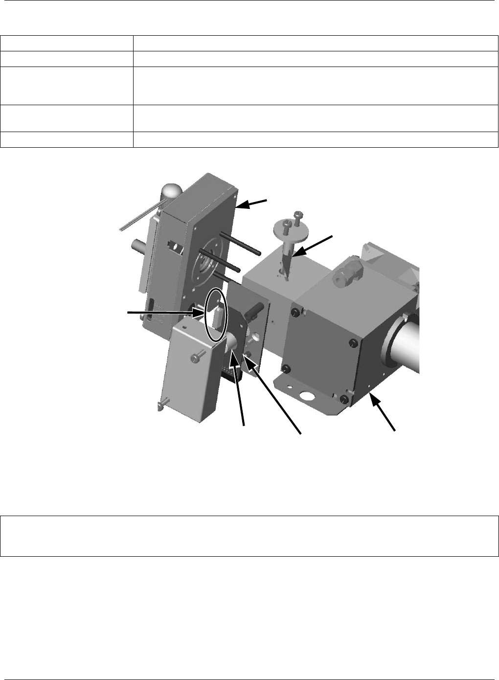
UV Reference
Detector
Adjustment
Pot
UV
Reference
Detector
PCA
Beam
Splitter
Reaction
Cell
Shutter
Housing
UV
Reference
Detector
Figure 10-4: Location of UV Reference Detector Potentiometer
5. Finger tighten the thumbscrew.
NOTE:
DO NOT over-tighten the thumbscrew.
07265A DCN6038