


TROUBLESHOOTING & REPAIR Teledyne API - T100H Addendum to T100 Operation Manual)
50
10.3.2.2. PMT Hardware Calibration (FACTORY CAL)
The sensor module hardware calibration adjusts the slope of the PMT output when the instrument’s slope and
offset values are outside of the acceptable range and all other more obvious causes for this problem have been
eliminated.
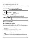
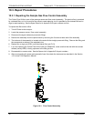
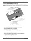
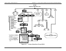
Figure 10-5: Pre-Amplifier Board Layout
1. Set the instrument reporting range type to SNGL (see Section 6.7.4 of the T100 Manual)
2. Perform a zero–point calibration using zero air (see Section 7 of the T100 Manual).
3. Let the instrument stabilize by allowing it to run for one hour.
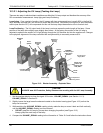
4. Adjust the UV Lamp. (See Section 10.3.2.1 of this addendum)
5. Perform a LAMP CALIBRATION procedure (see Section 6.9.7 of the T100 Manual).
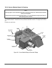
6. Locate the Preamp board (see Figure 3-4 of this addendum).
7. Locate the Following Components On the Preamp board (see Figure 10-5 of this addendum):
HVPS coarse adjustment switch (Range 0-9, then A-F)
HVPS fine adjustment switch (Range 0-9, then A-F)
Gain adjustment potentiometer (Full scale is 10 to 12 turns).
07265A DCN6038