


Theory Of Operation Teledyne API - T100H Addendum to T100 Operation Manual)
44
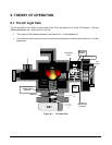
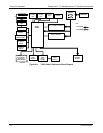
AC POWER
ENTRANCE
ON/OFF
SWITCH
Sample Gas
Pressure
Sensor
Motherboard
CPU
PS 1 (+5 VDC; ±15 VDC)
PS 2 (+12 VDC)
LVDS
Chassis
Cooling
Fan
PMT High
Voltage Supply
Temperature
Sensors
Vacuum
Pressure
Sensor
Sample
Chamber
Heaters
Sample/Cal
for Z/S and 2
Span Point
Valve Options
KEY
AC POWER
DC POWER
UV Source
Lamp
Power
Supply
PMT
Cooling
Fan
PMT
Preamp
UV Source
Lamp
Shutter
RELAY
BOARD
TEC
Control
PCA
UV Source
Lamp
Shutter
Dis
p
la
y
Touchscreen
USB
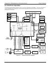
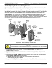
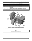
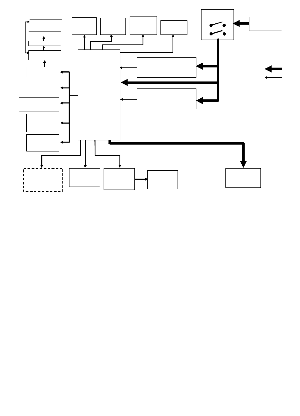
Figure 9-4: T100H Power Distribution Block Diagram
07265A DCN6038