


Teledyne API - T100H Addendum to T100 Operation Manual Operating Instructions
31
6.2.4. Default DAS Channels
The default Data Channels included in the T100H analyzer’s software include the CONC, PNUMT & CALDAT
channels. The FAST & DETAIL preset channels are not included.
6.2.5. Remote Operation Using the External Digital I/O
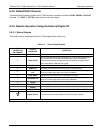
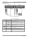
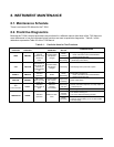
6.2.5.1. Status Outputs
The function and pin assignment5s for the T100H digital status outputs are:.
Table 6-5: Status Output Signals
SATUS
CONNECTOR
PIN NUMBER
1
STATUS
DEFINITION
CONDITION
1
SYSTEM OK
ON if no faults are present.
2
CONC VALID
OFF any time the HOLD OFF feature is active, such as during calibration or
when other faults exist possibly invalidating the current concentration
measurement (example: sample flow rate is outside of acceptable limits).
ON if concentration measurement is valid.
3
HIGH RANGE
ON if unit is in high range of the AUTO Range Mode
4
ZERO CAL
ON whenever the instrument’s ZERO point is being calibrated.
5
HIGH SPAN
CAL
ON whenever the instrument is set for DUAL or AUTO reporting range
mode an it’s high range span point is being calibrated .
6
DIAG MODE
ON whenever the instrument is in DIAGNOSTIC mode
7
LOW SPAN CAL
ON whenever the instrument is set for DUAL or AUTO reporting range
mode an it’s lows range span point is being calibrated .
8
SPARE
D
EMITTER BUS
The emitters of the transistors on pins 1-8 are bussed together.
SPARE
+
DC POWER
+ 5 VDC, 300 mA source (combined rating with Control Output, if used).
Digital Ground
The ground level from the analyzer’s internal DC power supplies
1
Located on Rear Panel
07265A DCN6038