


Theory Of Operation Teledyne API - T100H Addendum to T100 Operation Manual)
40
9.1.1. The Reference Detector
A vacuum diode UV detector that converts UV light to a DC current is used to measure the intensity of the
excitation UV source lamp. The location of the T100H reference detector differs from that of the T100.
On the T100 this detector is located directly across the reaction cell from the lamp where it can measure
the output of the lamp directly. Because the T100 is designed to measure relatively low concentrations
of SO
2
, enough of the lamp’s 214 nm source light makes it through the reaction cell to get a reliable
reading.
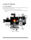
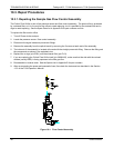
On the T100H the detector is located between the UV lamp and the reaction cell and to the side. A
beam splitter reflects a portion of the lamp output 90 degrees, through a window and onto the detector.
This arrangement is required because nearly all of 214 nm UV source light entering the reaction cell is
absorbed by the higher concentrations of SO
2
typically measured by the T100H.
A window transparent to UV light provides an air-proof seal that prevents ambient gas from contaminating the
sample chamber.
9.1.2. Direct Measurement Interferents
The most common source of interference when measuring SO
2
is from other gases that fluoresce in a similar
fashion to SO
2
when exposed to UV Light. The most significant of these are:
A class of hydrocarbons called poly-nuclear aromatics (PNA) of which xylene and naphthalene are two
prominent examples.
Nitric oxide (NO), which fluoresces in the a spectral range near to SO
2
. For critical applications where
high levels of NO are expected an optional 360 nm optical filter is available that improves the rejection of
NO (contact customer service for more information).
The methods by which the Model T100H rejects interference for these substances differs from the T100 as
follows.
Since the typical application for which the T100H rarely includes the presences of hydrocarbons or
PNA’s, no hydrocarbon scrubber (kicker) is included in the T100H’s base configuration. An optional
scrubber (see Section 5.3of this addendum) is available.
On the othe
r hand the typical T100H application often includes much higher concentrations of Nitric
Oxide (NO), which fluoresces in a spectral range near that of SO
2
. Therefore a 360 nm filter replaces
the 330nm UV filter located between the PMT and the reaction cell in order to more efficiently reject for
interference due to the higher concentrations of NO.
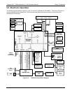
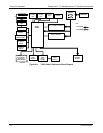
9.2. Pneumatic Operation
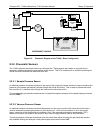
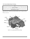
9.2.1. Sample Gas Flow
The flow of gas through the T100H UV Fluorescence SO2 Analyzer is created by a small external pump that
pulls air through the instrument. The T100H has no kicker to scrub hydrocarbons from the sample stream.
Typical applications for the T100H do not have hydrocarbons in the sample stream.
07265A DCN6038