


Operating Instructions Teledyne API - T100H Addendum to T100 Operation Manual)
32
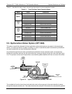
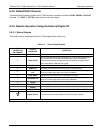
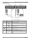
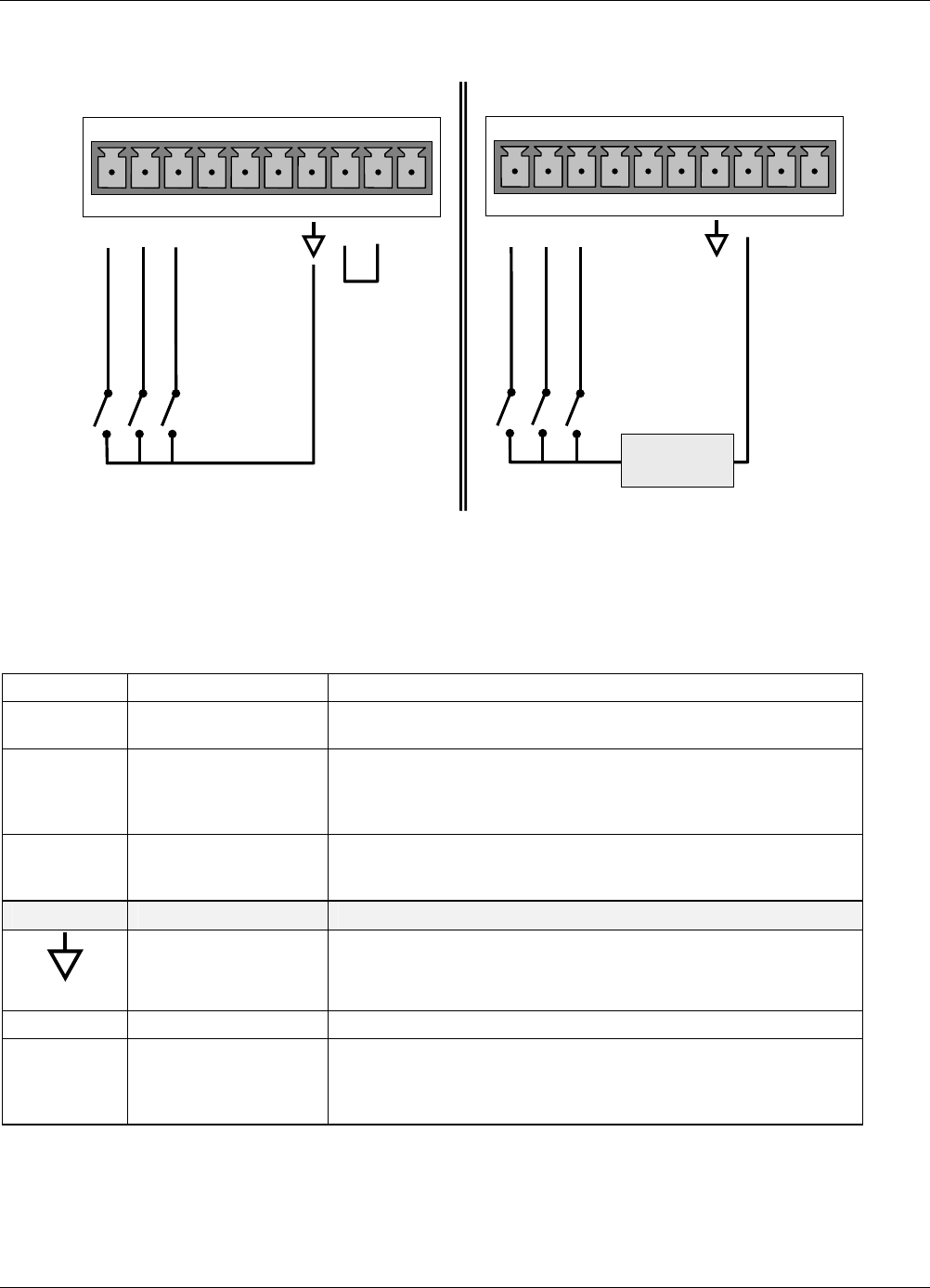
6.2.5.2. Control Inputs
ZERO CAL
HI SPAN CAL
ZERO CAL
CONTROL IN
A B C D E F U
+
HI SPAN CAL
CONTROL IN
A B C D E F U
+
-
+
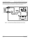
Local Power Connections
External Power Connections
5 VDC Power
Supply
LOW SPAN CAL
LOW SPAN CAL
Figure 6-1: Control Input Connector
Table 6-6: Control Input Signals
INPUT # STATUS DEFINITION ON CONDITION
A
REMOTE ZERO CAL
The analyzer is placed in Zero Calibration mode. The mode field of
the display will read ZERO CAL R.
B
REMOTE
HIGH SPAN CAL
If the instrument is set for DUAL or AUTO reporting rang mode,
activating this input causes the analyzer to enter high range span
calibration mode. The mode field of the display will read SPAN CAL
R.
C
REMOTE
LO SPAN CAL
The analyzer is placed in low span calibration mode as part of
performing a low span (midpoint) calibration. The mode field of the
display will read LO CAL R.
D, E & F
SPARE
Digital Ground
The ground level from the analyzer’s internal DC power supplies
(same as chassis ground)
U
External Power input
Input pin for +5 VDC required to activate pins A – F.
+
5 VDC output
Internally generated 5V DC power. To activate inputs A – F, place a
jumper between this pin and the “U” pin. The maximum amperage
through this port is 300 mA (combined with the analog output supply,
if used).
07265A DCN6038