


29
6. OPERATING INSTRUCTIONS
6.1. Warning Messages
Please refer to the T100 User’s Manual (06807), Section 4.2.2, for a list of warnings for the T100H. The
following table list describes an additional warning in the T100H.
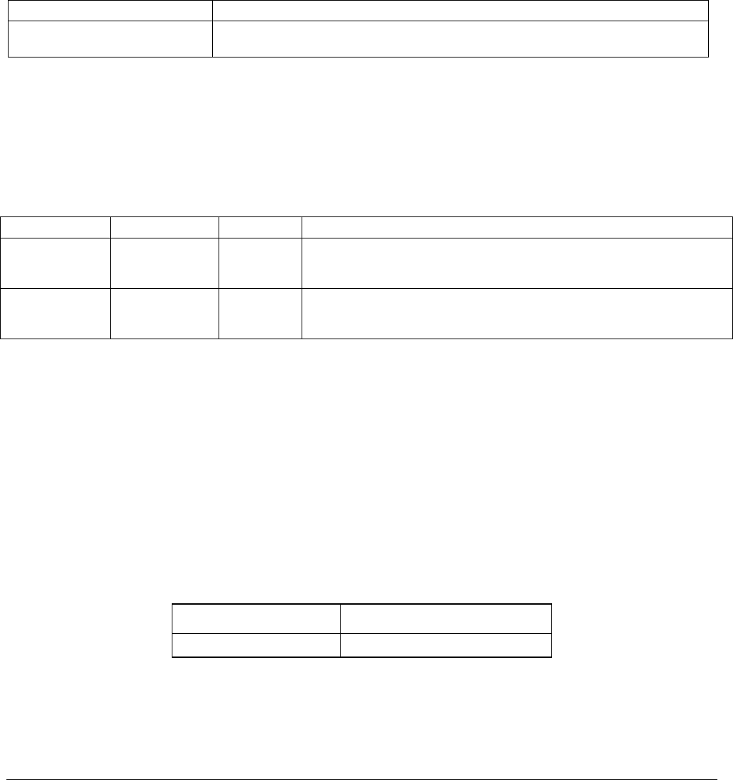
Table 6-1: Additional T100H Warning Messages
MESSAGE MEANING
Vacuum Pressure Warning
The vacuum pressure reading is out of its allowed range. The pump may have
failed, or the instrument may have a leak or obstruction in the flow path.
6.2. Test Functions
Please refer to the T100 Manual (06807), Section 4.2.1, for a list of test functions for the T100H. The following
table lists test functions that are in addition to or differ from those listed there.
Table 6-2: Additional T100H Test Functions
DISPLAY PARAMETER UNITS DESCRIPTION
VAC
Vacuum
Pressure
In-Hg-A
The actual pressure measured on the vacuum side of the T100H’s critical
flow orifice. This is the pressure of the gas in the instrument’s sample
chamber.
PRES
Sample GAS
Pressure
in-Hg-A
The current pressure of the sample gas as it enters the sample inlet at
the back of the analyzer, but upstream of the critical flow orifice and
before the gas enters the reaction cell.
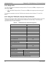
6.2.1. Test Channel Output
When activated, output channel A3 can be used to report one of the test functions viewable from the SAMPLE
mode display. To activate the A3 channel and select a test function, follow instructions in Section 6.9.10 of the
T100 Manual (P/N 06807).
The following table lists test functions that are in addition to or differ from those listed in Table 6-14 of the T100
Manual.
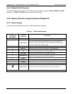
Table 6-3: Additional T100H Test Parameters Available for Analog Output A3
TEST CHANNEL TEST PARAMETER RANGE
VACUUM PRESSURE
0-40 in-Hg-A
07265A DCN6038