


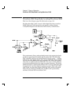
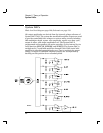

The ac mains are connected by a fused power entry module, P1.
This module incorporates the functions of mains connection, on/off
switching, fusing, and line voltage selection (100/120/220 (230)/240).
The line voltage selection function of module P1 selects which primary
winding of power transformer T1 is energized. The transformer
secondary windings are connected to the main pc board through
connector J1001.
The floating +5 Vdc and -5.2 Vdc supplies are produced by a bridge
rectifier formed by diodes CR1006 through CR1009, filter capacitors
C1005 and C1009, and voltage regulators U1003 and U1004. U1005 and
CR1011 form a clamp circuit to provide over voltage protection in the
event of a mains or transformer failure. The PFAIL and PONRST*
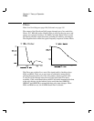
signals are derived from the floating +5 Vdc supply. PFAIL is asserted
when the raw 5 Vdc supply drops below 6.4 V signaling an unstable
power supply condition to the main CPU (U102). Current instrument
state information is copied to non-volatile RAM, U106 for future recall if
needed. The PONRST* signal holds the main CPU and other logic in a
reset state until after the +5 Vdc logic power supply is fully operational.
This signal is generally active only following application of line power to
the instrument.
The floating
18 volt supplies are produced by bridge rectifier CR1001,
filter capacitors C1001 and C1003, and regulators U1001 and U1002.
These supplies are used to power all analog circuits in the function generator.
In addition, the vacuum fluorescent display is driven from the
18 volt
supplies. A separate winding of T1 provides a center tapped 6 Vrms
filament supply for the display. Bias circuit CR1010, R1009, and C1011
generate the required cathode dc bias for the display filament supply.
The 5 volt earth referenced supply is produced by rectifier CR1051,
C1053, and regulator U1051. This supply is earth referenced through
the screw used to mount the PC board to the instrument chassis.
The GPIB (IEEE-488) and RS-232 computer interfaces and the rear-
panel EXT Trigger circuits are powered from this supply. A controlled
power-on reset signal for processor U903 is generated by U1052.
5
Chapter 5 Theory of Operation
Power Supplies
99