


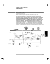
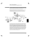
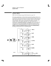

Transistors Q601 and Q602 buffer the output of the sine wave anti-alias
filter to the input of comparator U620. Square wave duty cycles are
controlled by the SQ_SYM input on the inverting input of the comparator.
The squarewave outputs of U620 are amplified by variable gain
amplifiers Q603 and Q604.
The amplifier gain output level is controlled by the variable current
source Q605 and U307D in response to the System DAC dc signal
SW_AMP. Squarewave variable gain amplifier output signal levels are
unbalanced by resistors R643 and R644 to correct for the output
amplifier + and - gain differences as discussed in the preattenuator
section on page 90.
Latching relay K601 connects the square wave into the +FUNCTION
and -FUNCTION paths. The relay set or reset state is selected by
momentarily pulsing the appropriate coil. Relay coils are pulsed with
5 volts for 15 ms through relay driver U301. The main controller, U102,
writes data bytes to ASIC U103 which transmits this data to the relay
drivers via the internal 3-wire serial data bus (SERCLK, SERDAT,
and SERSTB) to accomplish relay state changes.
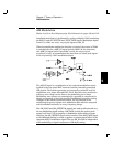
Multiplexer U604 selects one of five sources for the SYNC output: off,
modulation sync, square wave comparator output, RUN*, or Arbitrary
waveform sync. ARB_SYNC is derived from the WA14 line through
U210B. U215B and U210C control the pulse width of the ARB_SYNC
(arbitrary waveform sync) signal. Square wave sync is taken from the
inverting output of square wave comparator U620. U620 also generates
the MOD_SYNC (modulation sync) through U217. Buffer U621 inverts
the sync signal and provides the output current drive to the SYNC output
BNC connector.
5
Chapter 5 Theory of Operation
Square Wave and Sync
91