


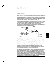
AM Modulation
Blocks 3 and 6 on block diagram page 129; Schematics on pages 136 and 133.
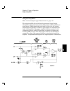
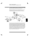
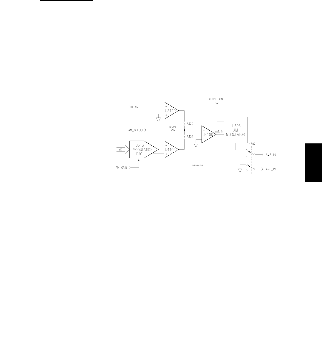
Amplitude modulation is performed by analog multiplier U603 combining
the AM_IN and +FUNCTION and -FUNCTION signals. Modulation depths
from 0% to 120% are set by varying the signal at AM_IN.
When the amplitude modulation function is selected, the output of U603
is switched into the +AMP_IN signal path by K602. At the same time,
the -AMP_IN signal path is grounded, cutting the output signal
amplitude in half, to accommodate the more than two times peak signal
levels required by >100% modulation depth.
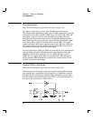
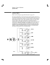
The AM_IN signal is a combination of any external modulation inputs
applied to the rear panel BNC connector and the internally generated
AM signals. The function generator can internally synthesize an 8-bit
modulation wave shape through DAC U313. Data from any standard or
arbitrary wave shape can be used as the modulating wave shape.
Modulating wave shapes are automatically expanded or compressed in
length, as required, to meet the specified modulating frequency setting.
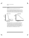
Changes in the function generator output will lag changes in the
modulating frequency because new modulation data must be computed
and downloaded internally for every frequency change.
The AM_GAIN and AM_OFFSET dc signals are used to calibrate and vary
the am modulation depth settings. AM_GAIN controls the peak-to-peak
output level from U313 in response to modulation depth setting changes.
Likewise, the AM_OFFSET signal varies inversely to the AM_GAIN signal,
as the AM depth setting is varied, to produce a constant signal offset in the
composite AM_IN modulation signal. The net AM_IN offset is independent
of the modulating ac signal component or AM depth setting.
5
Chapter 5 Theory of Operation
AM Modulation
89