


Distortion Verification
This test checks the Harmonic Distortion at selected frequencies and
harmonics. This test requires the use of a spectrum analyzer with
dynamic range, frequency range, and resolution bandwidth adequate for
the measurement.
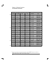
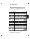
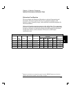
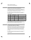
Select each function generator output in the table below. Use a spectrum
analyzer connected to the function generator output. Set the fundamental
frequency reference to 0 dB and measure the 2nd through 5th harmonic
frequencies relative to this reference. This test is a 50
W output
termination test.
Agilent 33120A Measurement
harmonic
Function
OUT
1
TERM
Ampl Freq Fundamental 2nd 3rd 4th 5th
Value below
reference
Sine wave
50 W
1.1 Vrms 20.00 kHz reference 40 kHz 60 kHz 80 kHz 100 kHz < 70 dB
Sine wave
50 W
1.1 Vrms 100.00 kHz reference 200 kHz 300 kHz 400 kHz 500 kHz < 60 dB
Sine wave
50 W
1.1 Vrms 1.00 MHz reference 2 MHz 3 MHz 4 MHz 5 MHz < 45 dB
Sine wave
50 W
1.1 Vrms 15.00 MHz reference 30 MHz 45 MHz 60 MHz 75 MHz < 35 dB
1
Output termination set using front panel controls. HIGH Z assumes no load on
output. 50W assumes a 50W 0.1W load on output.
4
Chapter 4 Calibration Procedures
Optional Performance Verification Tests
63