


Display and Keyboard
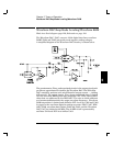
Block 11 on block diagram page 129; Schematic on page 141.
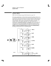
The front panel circuits consist of vacuum fluorescent display control,
display high voltage drivers, and keyboard scanning. Communication
between the front panel and floating logic circuits is accomplished
through a 4-wire bi-directional serial interface. The main CPU, U102,
can cause a hardware reset to processor U1101 by signal IGFPRES.
The front panel logic operates from -13 volts (logic 1) and -18 volts
(logic 0). The four serial communication signals are level shifted by
comparator U1301 from the floating logic 0 V to 5 V levels to the -18 V
to -13 V levels present on the front panel assembly. The front panel logic
high supply (-13 volts) is produced from the -18 volt supply by voltage
regulator U1102.
Display anode and grid voltages are +18 volts for an on segment and
-18 volts for an off segment. The -12 V cathode bias for the display is
provided by the main pc board’s filament winding center tap bias circuit
CR1010, R1009, and C1011 shown on the power supply schematic
(see page 140).
Keyboard scanning is accomplished through a conventional scanned
row-column key matrix. Keys are scanned by outputting data at
microprocessor U1101 port pins P0.0 through P0.4 to poll each key
column for a key press. Column read-back data are read by the
microprocessor at port pins P1.0 through P1.3 for decoding and
communication to the floating logic circuits. Rotary knob quadrature
inputs are read directly by the microprocessor port pins P1.6 and P1.7.
Chapter 5 Theory of Operation
Display and Keyboard
100