


DC Output Adjustment
The function generator stores nine calibration constants related to
DC volts output. The constants are calculated from the adjustment value
entered. The calibration constants are stored following completion of
setup 59. No calibration constants are stored if the procedures are aborted
at any other setup.
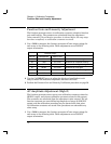
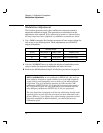
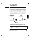
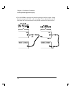
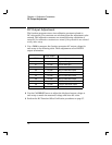
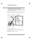
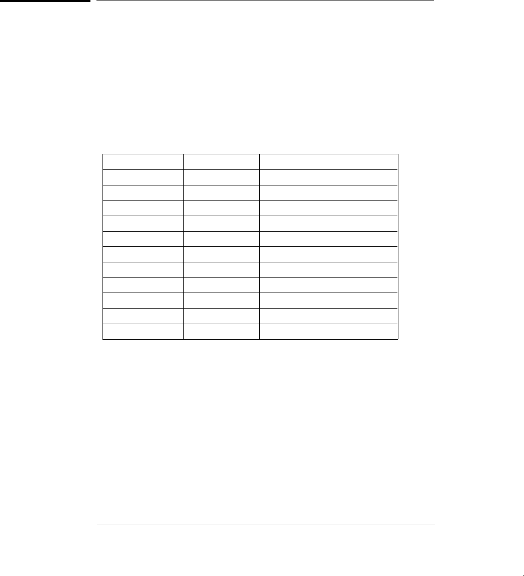
1 Use a DMM to measure the function generator dcV output voltage for
each setup in the following table. These adjustments use a HIGH Z
output termination.
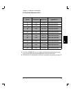
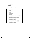
Nominal Output
SETUP DC Volts Adjustment for:
50 - 8.0 Vdc Negative offset gain
51 8.0 Vdc Positive offset gain
52 0.0 Vdc AM offset
53 0.0 Vdc 2 dB Pre-attenuator offset.
54 0.0 Vdc 4 dB Pre-attenuator offset.
55 0.0 Vdc 6 dB Pre-attenuator offset.
56 0.0 Vdc 8 dB Pre-attenuator offset.
57 0.0 Vdc 10 dB Pre-attenuator offset.
58 0.0 Vdc 12 dB Pre-attenuator offset.
59 0.0 Vdc 14 dB Pre-attenuator offset.
2 Use the CALIBRATE menu to adjust the displayed output voltage at
each setup to match the measured voltage and enter the value.
3 Perform the DC Function Offset Verification procedures on page 57.
Chapter 4 Calibration Procedures
DC Output Adjustment
76