


Modulation Adjustment
The function generator stores three calibration constants related to
amplitude modulation depth. The constants are calculated from the
adjustment value entered. If the calibration procedure is aborted before
all setup steps have been completed, no calibration constants are stored.
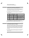
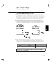
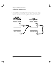
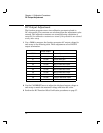
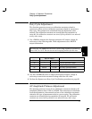
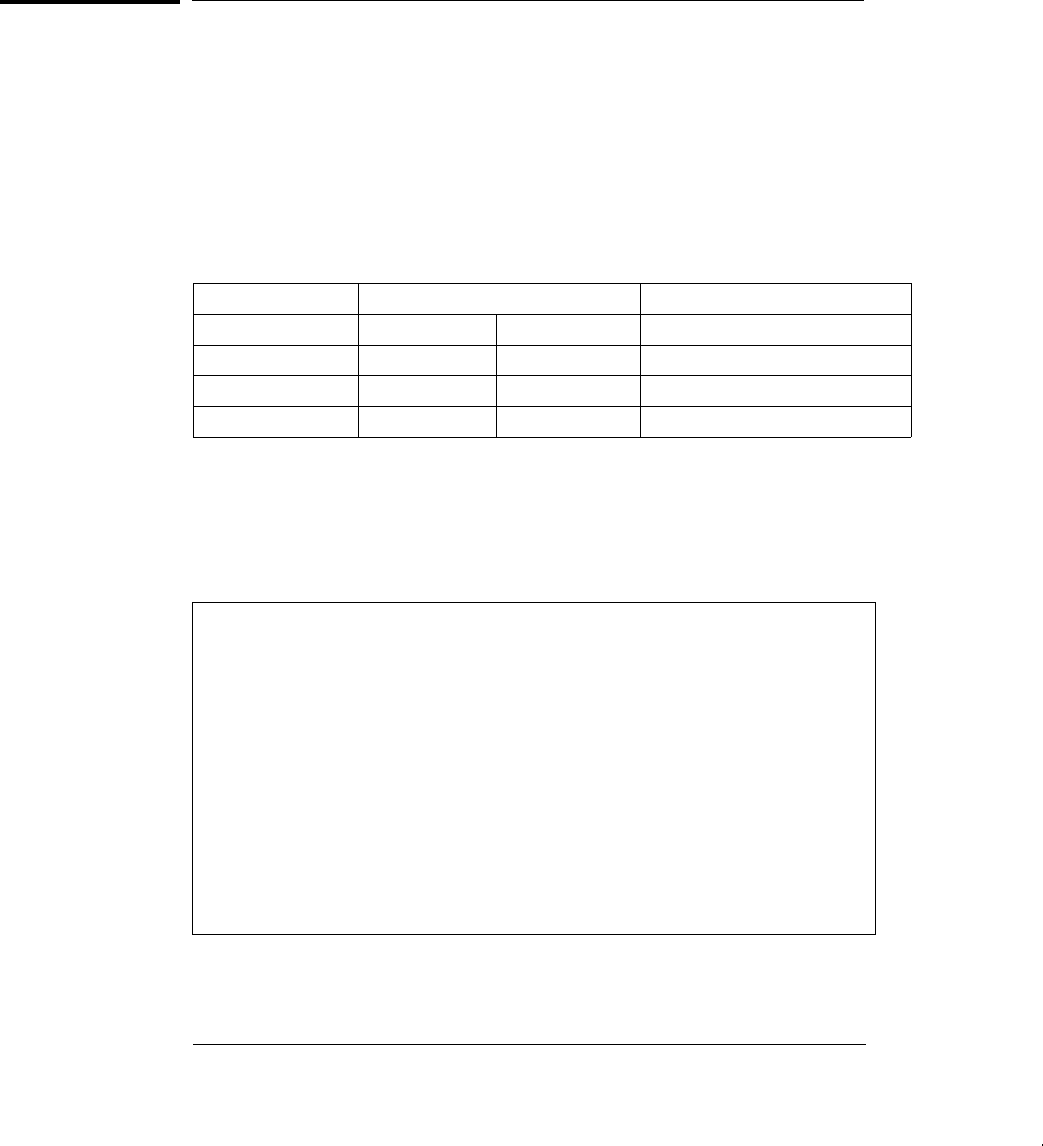
1 Use a DMM to measure the function generator ACrms output voltage for
each setup in the following table. These adjustments use a HIGH Z
output termination.
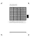
Nominal Output
SETUP FREQUENCY AMPLITUDE Adjustment for:
30 1 kHz 3.5 Vrms 0% modulation depth.
31 1 kHz 0.707 Vrms 50% modulation depth.
32 1 kHz 6.36 Vrms 100% modulation depth.
2 Use the CALIBRATE menu to adjust the displayed amplitude at each
setup to match the measured amplitude and enter the value.
33 Perform the AM Modulation Depth Verification procedures on page 61.
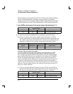
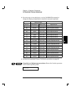
NEW CALIBRATION: A new calibration (SETUP 85 – Rev 4.0) has
been added to eliminate a small residual error in the AM amplitude
system which could potentially cause a failure of the AM amplitude
verification. The new calibration operates just like the other AM
calibrations (SETUP 30, 31, 32) in that the external measurement is
AC Vrms with no load. The new calibration is not allowed until the
other AM gain calibrations (SETUP 30, 31, 32) are performed.
The new algorithm is designed such that the calibration should not be
required again once the function generator has been calibrated at the
factory. However, if you change any critical analog components which
determine amplitude in AM modulation, you should perform the
calibration again.
Chapter 4 Calibration Procedures
Modulation Adjustment
72