


Function Gain and Linearity Adjustment
The function generator stores six calibration constants related to function
gain and linearity. The constants are calculated from the adjustment
value entered. If the calibration procedure is aborted before all setup steps
have been completed, no calibration constants are stored.
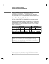
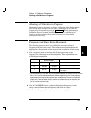
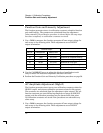
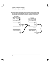
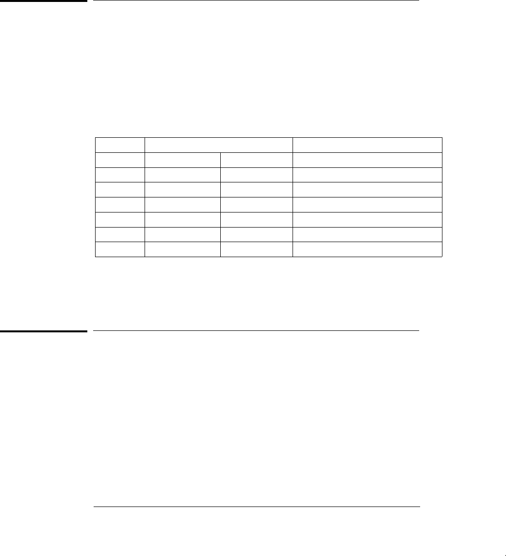
1 Use a DMM to measure the function generator ACrms output voltage for
each setup in the following table. These adjustments use a HIGH Z
output termination.
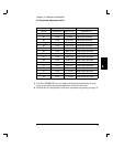
Nominal Output
SETUP FREQUENCY AMPLITUDE
02 1 kHz 7.07 V rms Adjustment for sine wave gain.
03 1 kHz 5.6 V rms Adjustment for amplitude linearity.
04 100 Hz 5.6 V rms Adjustment for triangle wave gain.
05 100 Hz 5.6 V rms Adjustment for ramp gain.
06 100 Hz 10.0 V rms Adjustment for square wave gain.
07 100 Hz 1.1 Vrms Adjustment for square wave linearity.
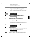
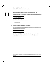
2 Use the CALIBRATE menu to adjust the displayed amplitude at each
setup to match the measured amplitude and enter the value.
3 Perform the Function Gain and Linearity Verification procedures on page 56.
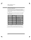
AC Amplitude Adjustment (High-Z)
The function generator stores twenty-two calibration constants related to
HIGH Z output, and sixteen calibration constants related to 50
W output.
The constants are calculated from the adjustment value entered. The cal-
ibration constants are stored following completion of setup 22 (HIGH Z
output) and the calibration procedure may be aborted after that point.
No calibration constants are stored if the procedures are aborted at any
other setup.
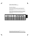
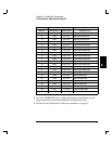
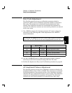
1 Use a DMM to measure the function generator ACrms output voltage for
each setup in the following table. These adjustments use a HIGH Z
output termination.
Chapter 4 Calibration Procedures
Function Gain and Linearity Adjustment
70