


Floating Logic
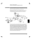
Block 1 on block diagram page 129; Schematic on page 131.
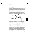
The floating logic controls the operation of the entire function function
generator. All output functions and bus command interpretation is
performed by the main CPU, U102. The front panel and earth referenced
logic operate as slaves to U102. The main CPU portion of the floating logic
section is clocked from a 12 MHz ceramic resonator, Y101. Non-volatile
EEPROM U106 stores arbitrary waveform data, calibration constants,
calibration secure code, calibration count, and last instrument state.
The main CPU, U102, is a 16-bit micro controller. The 16-bit A (address)
bus and 8-bit AD (address/data) bus are used to provide digital
communication with the 256k byte program ROM U104, 32k byte RAM
U105, 128k byte non-volatile EEPROM U106, 32k byte high speed
Modulation RAM U205, 16k x 12-bit high speed waveform RAM U404
and U405 and DDS ASIC U206.
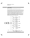
Gate array U103 provides CPU address latching and memory mapping
functions. There are four internal registers in U103: a configuration
register, an 8-bit counter register, a serial transmit/receive register, and
an internal status register. RAM chip select signal RAMCE* and CPU
port bits RAMA13 and RAMA14 are used to access 4 - 8k byte banks of
program data RAM. Similarly, 4 banks of 56k non-volatile EEPROM and
2 banks of 56k non-volatile RAM are gated from CPU port bits PRG16,
PRG17, and WAVA16 and U103 signal ROMCE*. Addresses on the CPU
address bus are valid when the ALE line is high. Memory mapping of
control of registers U107 and U202, DDS ASIC U206, data transceivers
U201, U203, U204, and write enables for RAM U404 and U405 and U205
are controlled by data selector U108.
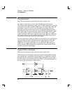
The U103 serial register controls the front panel, relay drivers U301 and
U302, and System DAC U303 through a serial data bus. Front panel
signals are FPDI, FPSK*, and FPDO. Interrupts from the front panel are
detected by U103 and signaled to U102 by CHINT. The FPINT line from
U102 signals the front panel that U103 has data to send. The internal
3-bit serial data bus (U102) uses SERCK, SERDAT, and SERSTB to send
data to various registers. SERRBK (serial read back) is used by self test
to verify operation of U103, relay drivers U301, U302, and System DAC
shift register U305.
5
Chapter 5 Theory of Operation
Floating Logic
97