


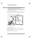
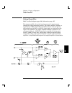
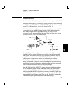
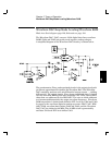
The block diagram shows four basic stages: dc amplifier, input differential
amplifier, gain, and power output. The amplifier’s input differential
amplifier stage and gain stage are symmetrical. The +AMP_IN and
-AMP_IN inputs are both amplified through complementary amplifiers
whose outputs are summed together at the input of the power output
stage. Transistors Q701, Q702, Q704 and Q707 form the complementary
input differential amplifiers. Q708 and Q705 are current sources which
provide bias to the input differential amplifiers. Q709 and Q710 are
emitter follower amplifiers used to couple the respective differential
amplifier outputs to the gain stage transistors Q711 and Q715 which
provide virtually all of the amplifiers open loop gain (~ x1000).
The power output stage is a wideband, class C buffer amplifier. Emitter
followers Q714 and Q716 buffer the gain stage output from loading by the
power output emitter follower transistors Q713 and Q718. Idle current
bias for these power output transistors is set by the ratios of R732, R726
and transistor matching between Q713, Q714 and their equivalents in
the other half of the stage: R734, R727 and Q718, Q716. Transistors Q712
and Q717 are current sources which provide bias to emitter followers
Q714 and Q716 respectively.
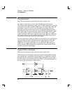
The low frequency and dc performance of the amplifier is controlled by
U702. This amplifier is used to sense the dc offset present at the
+AMP_IN and -AMP_IN inputs and servo the output amplifier dc offset
to zero volts; to the limit of U702’s own dc offset performance. U702 also
provides a means to add a desired dc offset value into the output signal
path through the x (-1) gain of the OUT_OFFSET signal.
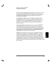
The output amplifier employs a current feedback technique to set the
closed-loop gain. The emitters of Q701 and Q702 are the virtual summing
node points in the amplifier. Amplifier closed loop gain is controlled
predominately by the following ratios:
2 R740 R710 R717
R715 R716
and
2 R740 R710 R711
R719 R720
Variable resistor R710 is used to match the gain through the high frequency
feedback path (described above) and the dc feedback path summed
through resistors R705, R706. The feedback signal current is injected into
the amplifier through the emitters of Q701 and Q702 respectively.
Chapter 5 Theory of Operation
Output Amplifier
88