


Frequency Verification
This test verifies the frequency accuracy of the two sources in the
function generator. All output frequencies are derived from a single
generated frequency, and only one frequency point is checked.
The second test verifies the burst rate frequency.
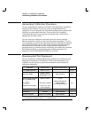
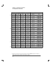
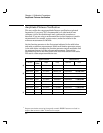
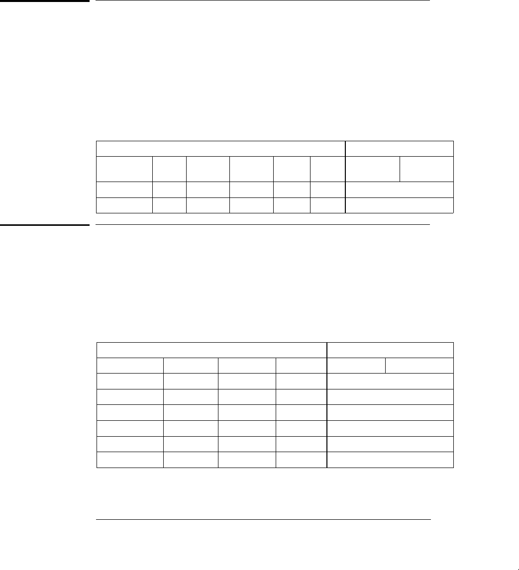
Set the function generator for each output indicated in the table below.
Use a frequency meter to measure the output frequency. Compare the
measured results to the test limits shown in the table. This is a 50
W
output termination test.
Agilent 33120A Measurement
Function
OUT
1
TERM
Ampl Freq
BURST
RATE
BURST
CNT
Nominal Error
Q Sine wave
50 W
3.5 Vrms 1.00 kHz — — 1.00 kHz
0.02 Hz
Q Square wave
50 W
3.5 Vrms 1.00 kHz 500 Hz 1 CYC 500 Hz
5 Hz
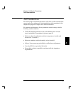
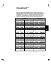
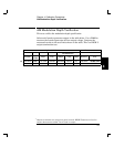
Function Gain and Linearity Verification
This test verifies the output amplitude accuracy specification for
sine wave, triangle wave, ramp, and square wave outputs.
Set the function generator for each output indicated in the table below.
Use a DMM to measure the function generator ACrms output voltage.
Compare the measured results to the test limits shown in the table.
This is a HIGH Z output termination test.
Agilent 33120A Measurement
Function OUT TERM
1
Ampl Freq Nominal Error
Q Sine wave HIGH Z 7.0 Vrms 1.0 kHz 7.0 Vrms
0.07 Vrms
Sine wave HIGH Z 5.7 Vrms 1.0 kHz 5.7 Vrms
0.057 Vrms
Triangle wave HIGH Z 5.7 Vrms 100 Hz 5.7 Vrms
0.057 Vrms
Ramp wave HIGH Z 5.7 Vrms 100 Hz 5.7 Vrms
0.057 Vrms
Q Square wave HIGH Z 10.0 Vrms 100 Hz 10.0 Vrms
0.1 Vrms
Square wave HIGH Z 8.0 Vrms 100 Hz 8.0 Vrms
0.08 Vrms
1
Output termination set using front panel controls. HIGH Z assumes no load on
output. 50W assumes a 50W 0.1W load on output.
Chapter 4 Calibration Procedures
Frequency Verification
56