


Output Attenuator
Block 8 on block diagram page 129; Schematic on page 138.
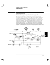
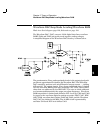
The Output Attenuator provides 0 to 30 dB of signal attenuation between
the output amplifier section and the output BNC connector. Output signal
levels are controlled by combining coarse amplitude control from the
output attenuator section and pre-attenuator section with fine amplitude
control from the Waveform DAC AMP_CTL signal.
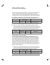
Four switched output attenuator pads are combined to achieve the desired
signal attenuation as shown in the table below. Relays K801 through
K804 either bypass an attenuator pad or select that attenuator. K801
selects a 2 dB attenuator, K802 selects a 4 dB attenuator, K803 selects
a 8 dB attenuator, and K804 selects a 16 dB attenuator. Relays are
sequenced to provide signal attenuation in 6 dB steps. Intermediate
amplitude levels are controlled by selecting 0 dB, 2 dB or 4 dB of signal
attenuation through the pre-attenuator solid state switches in
combination with reducing the output level of the waveform DAC itself.
The AMP_CTL signal provides smoothly varying control of the Waveform
DAC output level over a 0 dB to -2 dB range. This operation is described
further in the Waveform DAC and System DAC discussions.
Output Attenuation K801 K802 K803 K804
0 dB set set set set
6 dB reset reset set set
12 dB set reset reset set
18 dB reset set set reset
24 dB set set reset reset
30 dB reset reset reset reset
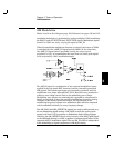
K801 through K804 are latching relays. Their set or reset state is selected
by momentarily pulsing the appropriate coil of the relay. Relay coils are
pulsed with 5 volts for 15 ms through relay drivers U301 and U302.
The main controller, U102, writes data bytes to ASIC U103 which
transmits this data to the relay drivers via the internal 3-wire serial data bus
(SERCLK, SERDAT, and SERSTB) to accomplish the relay state changes.
A 30 MHz filter, composed of L801, C801, and C802, eliminates wideband
noise from the function generator output. The output amplifier and output
attenuators are protected from damage by clamps CR801 and CR802 and
by fuse F801. The function generator is protected from accidental
application of voltages <10 volts for short durations.
Chapter 5 Theory of Operation
Output Attenuator
86