


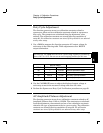
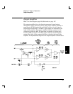
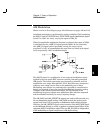

Block Diagram Overview
This discussion pertains to the block diagram shown on page 129.
The function function generator’s circuitry is divided into two major
blocks: the floating section and the earth (ground) reference section.
All signal generation, control, and display functions are contained in
the floating section. This section also contains the function generator’s
main CPU.
The floating section can be viewed in two pieces; the analog signal
conditioning section (System DAC, Filters, Sync, Square wave,
Pre-Attenuator, Output Amp, and Output Attenuator) and the digital
logic section (Floating Logic, Digital Waveform Data Synthesis, and
Waveform DAC).
All signal generation, level control, and modulation functions are
performed in the floating section. The waveform DAC generates two
outputs, normal and inverted, between approximately 800 mVp-p and
1 Vp-p. The DAC outputs are routed through anti-alias low-pass filters to
eliminate higher frequency sampling products. The nominal x10 gain of
the output amplifier, combined with preattenuator and output attenuator
settings, are chosen such that the desired output amplitude is produced.
The ground reference section uses a processor configured as a slave to the
main CPU. This processor establishes external I/O communication with
the main CPU through a bi-directional, optically isolated, serial
communications link. The earth referenced processor controls low-level
GPIB (IEEE-488) and RS-232 interface operation. The ground referenced,
rear panel external trigger input uses a dedicated optical isolator to
couple a trigger signal to the main CPU in the floating section.
Separate power supplies are provided for the floating and ground
reference sections. The front panel operates from the floating section with
its logic common different from the CPU logic common.
5
Chapter 5 Theory of Operation
Block Diagram Overview
85