


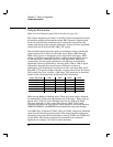
Pre-attenuator
Block 6 on block diagram page 129; Schematic on page 136.
All signals, except square waves, pass through the preattenuator.
The preattenuator multiplexes eight resistive 2 dB attenuators to provide
attenuation from 0 dB to 14 dB in 2 dB steps. The 0 dB, 2 dB, and 4 dB
attenuation steps are used for level settings between the 6 dB steps
selected in the output attenuator section. Amplitude settings between
these 2 dB steps are set by smoothly varying the Waveform DAC output
level from 0 dB to -2 dB of its nominal level via the AMP_CTL signal.
Output attenuator 6 dB steps, preattenuator 0 dB, 2 dB, and 4 dB steps,
and small variations (0 dB to 2 dB) of the Waveform DAC output level
are combined to produce each amplitude setting.
In the preattenuator, U601 and U602 are operated as 8-to-1 multiplexers,
each providing selectable 2 dB attenuation steps. Because of the gain
imbalance of the output amplifier (x 12 on +AMP_IN and x (-10) on
-AMP_IN), the +signal path U601 has an additional 2 dB attenuation
always present (R601 and R602) to equalize the nominal gains in both
the plus and minus signal paths.
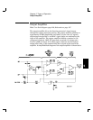
Square Wave and Sync
Block 6 on block diagram page 129, schematic on page 136.
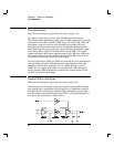
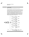
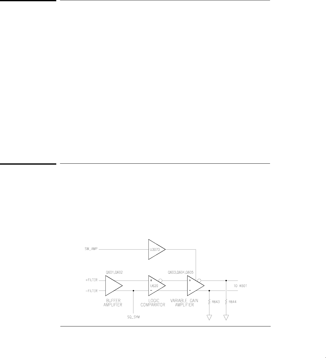
During square wave outputs, a sine wave signal is generated internally
and squared-up by comparator U620. Square wave amplitude control is
accomplished by variable gain amplifier Q603 and Q604 and switched
into the output signal path through relay K601. A simplified diagram of
the square wave generator is shown below.
Chapter 5 Theory of Operation
Pre-attenuator
90