


19
This prevents any dirt or foreign particles from
entering the compressor and contaminating the
working parts. The oil should then be charged
into the compressor.
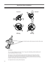
Charge a small amount of ammonia into the sys-
tem and pressurize the system to its respective
design pressure. Pass a lit sulfur stick around all
joints and connections. Any leaks will be indi-
cated by a heavy cloud of smoke. If any leaks are
observed during this test, they must be repaired
and rechecked before the system can be consid-
ered tight and ready for evacuation.
B. Halocarbon Refrigerant Systems
“Oil pumped” dry nitrogen, or anhydrous CO
2
in
this order of preference may be used to raise the
pressure to the proper level for testing.
When the proper pressure is attained, test for
leaks with the soap mixture previously described.
After all leaks are found and marked, relieve the
system pressure and repair the leaks. Never at-
tempt to repair soldered or welded joints while
the system is under pressure. Soldered joints
should be opened and re soldered.
Do not simply add more solder to the leaking
joint. After all the joints have been repaired and
the system is considered “tight” the system may
be tested with refrigerant.
Attach a drum of the refrigerant to be used in the
system and allow the gas to enter until a pressure
of 5 psig is reached.
Remove the refrigerant drum and bring the
pressure to the recommended test level with oil
pumped dry nitrogen or CO
2
. Then check the
entire system again for leaks, using a halide torch
or electronic leak detector. Be sure to check all
anged, welded, screwed and soldered joints, all
gasketed joints, and all parting lines on castings.
If any leaks are found, they must be repaired and
rechecked before the system can be considered
tight again, remembering that no repair should
be made to welded or soldered joins while the
system is under pressure.
C. Evacuating The System
A refrigeration system operates best when only
refrigerant is present. Steps must be taken to
remove all air, water, vapor, and all other non-
condensables from the system before charging it
with refrigerant. A combination of moisture and
refrigerant, along with any oxygen in the system,
can form acids or other corrosive compounds that
corrode internal parts of the system.
To properly evacuate the system, and to remove
all non-condensables, air and water vapor, use a
high vacuum pump capable of attaining a blanked
off pressure of 50 microns or less. Attach this
pump to the system and allow it to operate until
system pressure is reduced somewhere below
1000 microns. Evacuation should not be done
unless the room temperature is 60F or higher.
Attach vacuum gauge(s), reading in the 20 to
20,000 micron gauge range, to the refrigerant
system. These gauge(s) should be used in con-
junction with the high vacuum pump. The read-
ing from the gauge(s) indicates when the system
has reached the low absolute pressure required
for complete system evacuation.
Connect the high vacuum pump into the re-
frigeration system by using the manufacturer’s
instructions. Connect the pump both to the high
side and low side of the system, to insure system
evacuation. Attach the vacuum gauge to the
system in accordance with the manufacturer’s
instructions.
A single evacuation of the system does not satis-
factorily remove all of the non-condensable, air
and water vapor. To do a complete job, a triple
evacuation is recommended.
When the pump is rst turned on, bring system
pressure to as low a vacuum level as possible, and
continue operation for 5 to 6 hours.
Stop the pump and isolate the system. Allow
the unit to stand at this vacuum for another 5 to
6 hours. After this time, break, the vacuum and
bring the system pressure up to 0 psig with dry
nitrogen.
Installation