


71
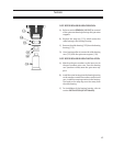
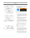
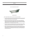
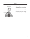
DISCHARGE MANIFOLD INSTALLATION
A) Install (2) guide rods to position the discharge
manifold. Install a new manifold gasket and
the discharge manifold. Install the dowel pins
and bolts, tighten manifold bolts to the recom-
mended torque value.
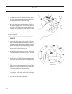
B) On VSS 451-3001 compressors install the dis-
charge spool or elbow between the discharge
manifold and oil separator with new gaskets.
When installing the discharge elbow tighten
the bolts to the correct torque on the manifold
flange first before tightening the separator
ange bolts. Install the drain plug in the bottom
of the discharge manifold.
C) On VSM 301-701 compressors install the bolts
in the discharge ange. Install the drain plug in
the bottom of the discharge manifold.
D) Install both command shaft assemblies and
control actuators.
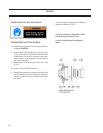
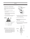
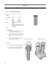
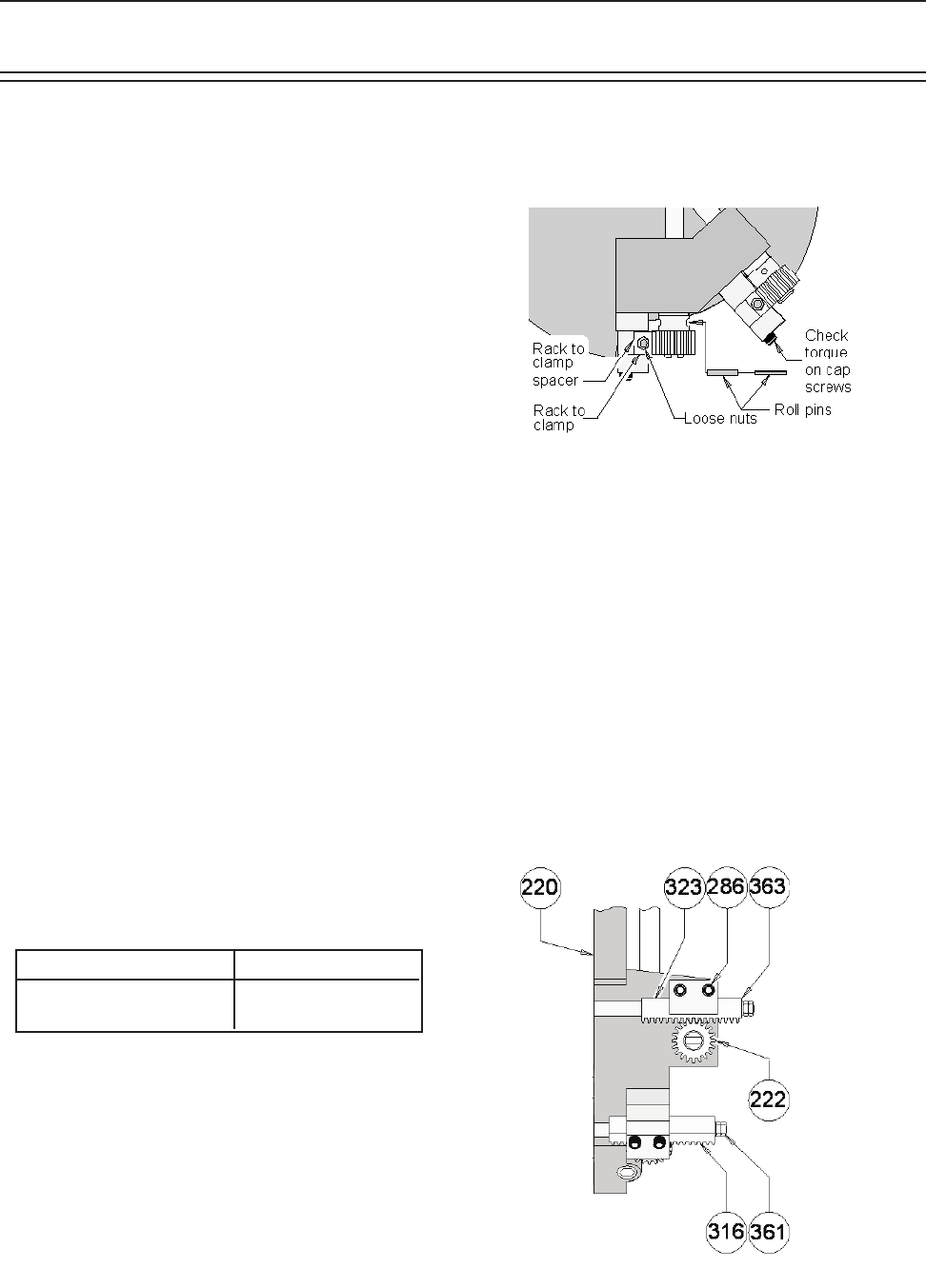
SLIDE VALVE GEAR AND RACK INSPECTION
A) Remove the discharge manifold.
B) Check rack to rack clamp and rack clamp spacer
clearance on all four slide valves.
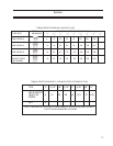
TABLE 4.1
RACK CLEARANCE VALUES
C) Check torque of socket heat cap screws.
D) Check for excessive movement between the
slide valve rack shafts and the rack. The jam nuts
on the end of the slide valve rack shaft should be
tight.
E) Check for loose or broken roll pins in gears.
Service
F) Look for any excessive wear on all moving parts
and replace the worn parts.
G) Reassemble the manifold and discharge elbow.
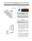
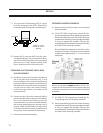
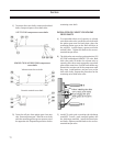
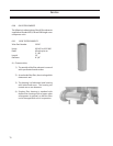
REMOVAL OF CAPACITY OR VOLUME CROSS
SHAFTS
A) Remove the discharge manifold.
B) To remove the capacity or volume ratio slide
valve racks, remove the two jam nuts and lock
washers (361) securing the rack (316) to the slide
valve shafts. The racks can now be pulled off the
slide valve shafts. Repeat the procedure for the
remaining pair of slide valve racks.
MEASUREMENT CLEARANCE
Rack to clamp. 0.005 to 0.010”
Rack to clamp spacer. 0.003 to 0.005”