


69
COMMAND SHAFT ASSEMBLY REMOVAL
The following steps can be used to remove or install
either the capacity or volume command shaft as-
semblies.
A) Prepare the compressor for servicing.
B) Follow the appropriate instructions to remove
control actuator.
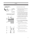
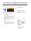
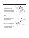
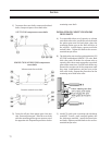
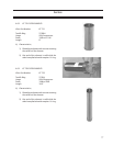
C) Remove four socket head cap screws (457) and
Nord-Lock washers (477) securing mounting
plate (415) to manifold.
D) The command shaft and mounting plate may
now be removed from the compressor.
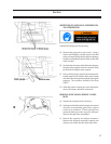
COMMAND SHAFT ASSEMBLY INSTALLATION
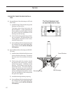
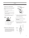
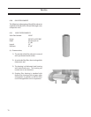
A) Install the command shaft assembly with a new
o-ring (446) on the manifold. Make sure that the
command shaft tongue is engaged in the cross
shaft slot. Rotate the bearing housing so the
vent holes point down, this will prevent water
and dust from entering the vents.
Service
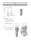
B) Install the actuator mounting plate with the four
socket head cap screws and Nord-Lock washers
securing it with proper torque.
C) The unit can now be leak checked.
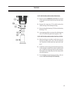
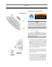
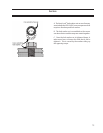
COMMAND SHAFT BEARING AND O-RING SEAL
REPLACEMENT
A) Remove command shaft assembly.
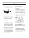
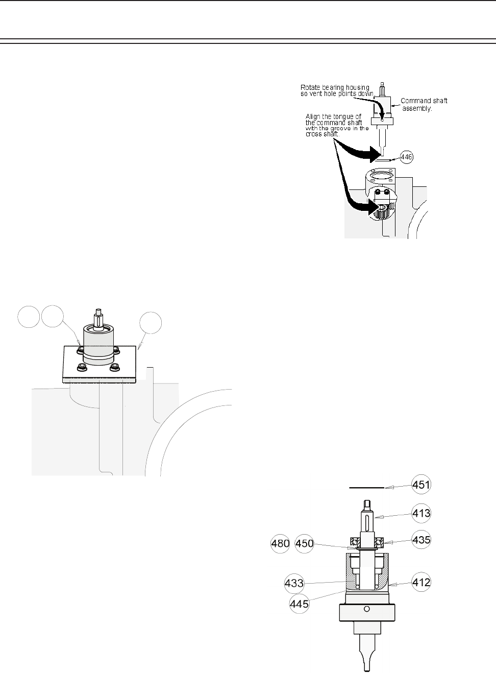
B) Remove snap ring retainer (451) from command
shaft housing (412). Push the command shaft as-
sembly out of the housing.
4 57
4 77
4 15