


40
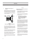
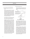
1.2 The actuator mounts on the ball valve stem.
Flats on the ball valve stem indicate the position
of the ball:
OPEN – stem flats are with the flow
CLOSED – stem flats are across the flow
1.3 On smaller valves, the ball valve stem flats
are nearly hidden between the stem extension
and the stem lock nut. The locking tabs on the
stem lock nut are across the flow.
1.4 The actuator position indicator stem flats
are oriented in the same direction as the ball
valve stem flats.
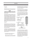
1.5 There is a mechanical position indicator on
the top of the actuator cover.
NOTE: The oil temperature control valve comes
from the vendor already assembled with the ball
closed and the actuator in the CLOSED position.
2. Control Action
2.1 The ball valve can rotate through a full 360°
arc.
2.2 The actuator restricts the ball to a 90° arc of
travel.
2.3 The actuator is powered (120V or 24V) all
the time.
2.4 The position target signal from the com-
pressor controller is a 4-20mA analog value.
2.5 There is no feedback position from the ac-
tuator.
3. Initial Position
3.1 With the electrical power to the valve de-
energized, the valve is set to its initial position
by ensuring that the ball is in the closed position
and that the actuator indicator displays CLOSED.
3.2 When the electrical power to the valve is
energized, the valve should rotate to fully OPEN.
4. Operation
4.1 When initially installed, the ball must be in
the closed position.
4.2 When electrically energized, if the compres-
sor is not running, the compressor controller will
turn the valve fully open (100%).
4.3 When the compressor starts, the valve
remains fully open (100%) until the oil injection
temperature rises above the control setpoint.
4.4 When the oil injection temperature rises
above the control setpoint, the oil temperature
control valve will begin to close.
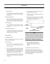
4.5 The hot oil from the oil separator begins
to divert to the oil cooler, mixing the hot and
cooled oil flow streams together downstream
of the oil temperature control valve. The valve
can fully close (0%) diverting the entire oil flow
stream to the oil cooler.
4.6 As the oil injection temperature drops be-
low the setpoint, the oil temperature control
valve begins to open so that the oil injection
temperature does not become too cold.
4.7 When the compressor stops, the valve re-
turns to fully open (100%).
5. Fail Position
The actuator remains in its last position when
power is removed.
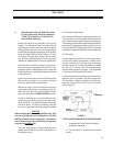
6. Screen Display
The oil temperature control valve, identified
as “OIL MIX” on the main HMI display screen,
shows a numerical value with “%” as units. This
is to be understood as “% OPEN.” It is a direct
indication of the position of the ball valve.
6.1 100% OPEN
oil flow stream is entirely bypassing the oil cooler
Operation