


53
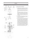
Drive End
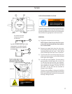
GATE ROTOR ASSEMBLY CAUTION
Gate rotor removal and assembly is divided into dis-
tinct instructions, instructions for all VSG and VSSG
models and different instructions for all VSM models.
Please follow the appropriate set of instructions.
REMOVAL
A) Prepare the compressor for servicing.
NOTE: All parts must be kept with their appro-
priate side and not mixed when the compres-
sor is reassembled.
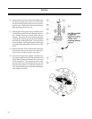
B) Remove two upper bolts from the side cover,
and install guide studs in the holes. Remove the
remaining bolts and side cover. There will be
some oil drainage when the cover is removed.
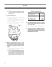
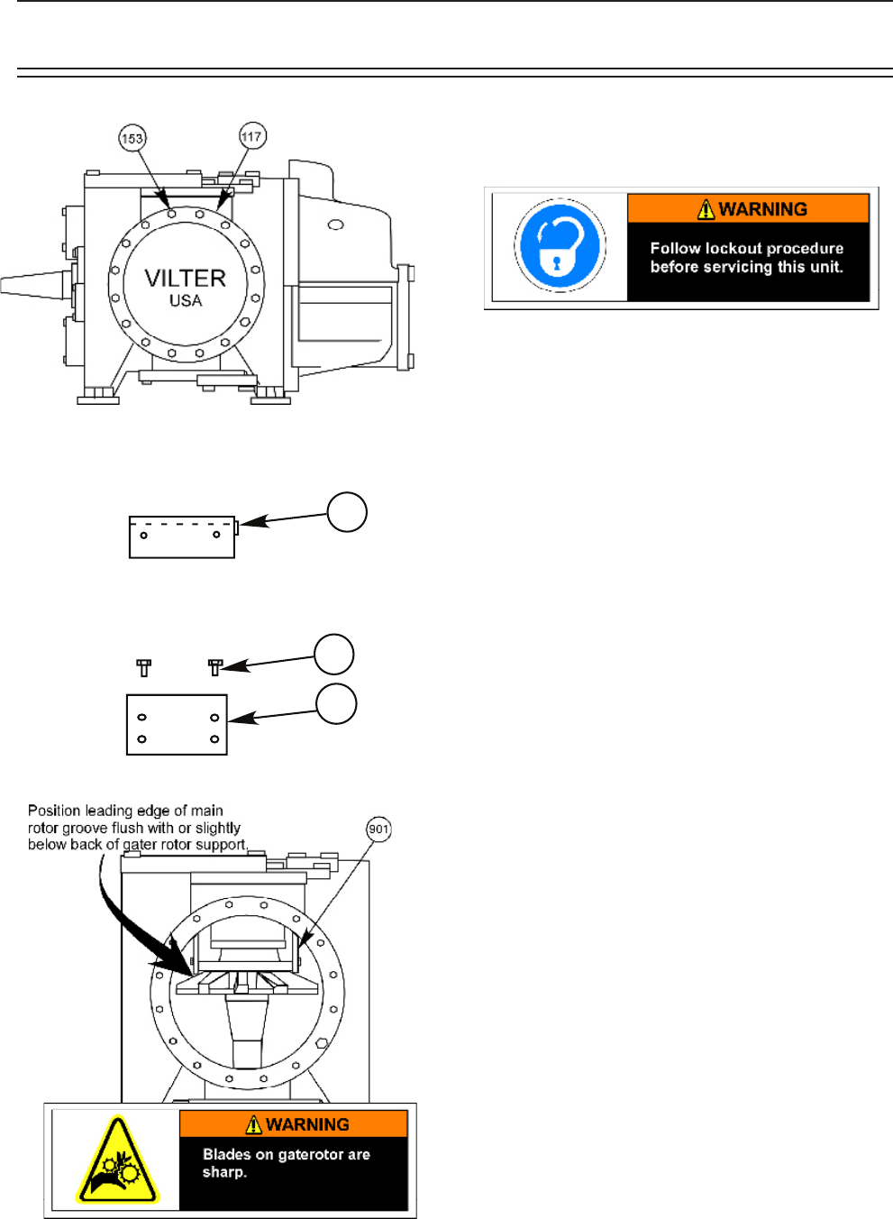
C) Turn the main rotor so a driving edge of any one
of the main rotor grooves is even with the back
of the gate rotor support.
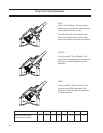
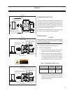
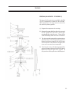
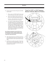
D) Insert the gate rotor stabilizer. The side rails are
not required on VSS 451 thru 601. For the VSS
751 thru 901 and VSS 1051 thru 1201 compres-
sors, use the side rails and assemble to the gate
rotor stabilizer as stamped. For the VSS 1551
thru 3001, use the side rails and assemble to
the gate rotor stabilizer.
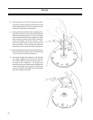
The gate rotor stabilizer is designed to hold the
gate rotor support in place and prevent damage
to the gate rotor blade as the thrust bearings and
housing is being removed.
Service
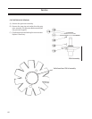
901C
901B
901A
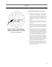
For VSM 451 thru 601
compressors, do not
use side rails.
For VSS 751/901 & VSS 1051/1201
compressors, use side rails and
assemble to gaterotor stabilizer
as stamped.