


46
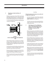
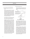
Field Piping and Mechanical Requirements
NOTE: If start-up service has been purchased, the following items should be completed before the start-
up technician arrives. This will help save time and money.
1. The unit should be leveled and secured to the mounting pad or floor.
2. The suction and Discharge line must be piped and properly supported, independent of the unit
3. The Discharge Stop/Check Valve is shipped loose and must be installed in a vertical up flow direction or
in a horizontal line with the valve stem pointing upward at a 45° angle. During off periods, refrigerant
can condense in the line downstream of the Discharge Stop/Check Valve. It is recommended the Stop/
Check Valve be located to minimize the quantity of liquid that can accumulate downstream of the valve.
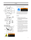
4. A Dual Safety Relief Valve is shipped loose for field installation. A connection is provided on the oil sepa
rator for the relief valve. Refer to ASHRAE/ANSI Standard 15 (Safety Code for Refrigeration) for proper
sizing and installation of Relief Valves and Vent Lines.
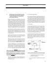
5. Piping For Oil Cooling
a) Liquid Injection
An adequate, or dedicated, liquid line is required for the Liquid Injection System. A high pressure
liquid source must be piped to the stop valve at the inlet of the Thermostatic Expansion Valve. On
booster units, an additional
3
/
8
” line must be piped to the regulator from high stage discharge gas flow
or the Thermostatic Expansion Valve.
b) V-PLUS
A high pressure liquid source must be run to the V-PLUS
®
inlet. Some subcooling is desirable. A
high pressure float must be installed at the inlet of the pump and a
3
/
8
” vent line must be returned to
a suction trap. Refer to the V-PLUS manual for additional information.
c) External Oil Cooler
On thermosyphon oil coolers, the refrigerant lines must be connected to the front head of the oil
cooler. On water cooled oil coolers, the water lines must be connected to the front head of the oil
cooler. Installation of water regulating and solenoid valves are recommended.
6. The oil separator should be provided with oil until the oil level is between the (2) sight glasses. An oil
charging connection is provided on the bottom of the oil separator.
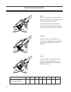
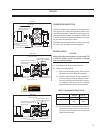
7. The center member of the compressor coupling is shipped loose to help facilitate final field alignment
and allow for motor rotation check. The motor alignment should be within 0.004” total indicator read
ing in all directions.
a) Both the compressor and motor hubs should be checked for concentricity and perpendicularity.
b) The motor should be checked and shimmed for soft foot prior to attempting final alignment.
c) The center section of the coupling should be left out to allow the start-up technician to verify the
final alignment and motor rotations.
8. The unit should be pressure tested, evacuated and a system load should be available at the
time of start-up.
Order #_______________________________Compressor Serial #________________________