


26
will result in a exing element that is centered and
parallel to its mating ange faces. Move the con-
nected equipment to accomplish the above.
NOTE: The disc pack is designed to an optimal thick-
ness and is not to be used for axial adjustments.
See documentation that came with the coupling for
complete specications.
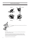
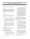
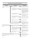
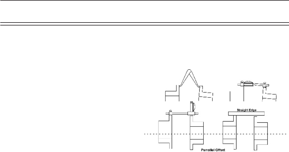
3. Angular Alignment. Rigidly mount a dial indicator
on one hub or shaft, reading the face of the other
hub ange, as shown on next page. Rotate both
shafts together, making sure the shaft axial spacing
remains constant. Adjust the equipment by shim-
ming and/or moving so that the indicator reading
is within .002 inch per inch of coupling ange.
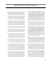
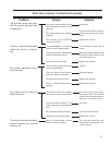
4. Parallel Offset. Rigidly mount a dial indicator on
one hub or shaft, reading the other hub ange out-
side diameter, as shown in Figure 3. Indicator set-up
sag must be compensated for. Rotate both shafts
together. Adjust the equipment by shimming and/
or moving so that the indicator reading is within
.002 inch per inch of the axial length between ex
elements. See drawing below.
Note: If the driver or driven equipment alignment
specication is tighter than these recommendations,
the specication should be used. Also, be sure to
compensate for thermal movement in the equipment.
The coupling is capable of approximately four time
the above shaft alignment tolerances. However, close
alignment at installation will provide longer service
with smoother operation.
E. Final assembly
With the coupling in good alignment the bolts will t
through the holes in the anges and the disc packs
more easily.
1. If the coupling arrived assembled, the disc packs
are still attached to the center ring. Before tak-
ing the discs packs off, rst install one hub bolt
through each disc pack and secure with lock out.
This will help when the pack is reinstalled late. If
the coupling was shipped disassembled, the bolt
through the pack is not required as the discs in the
pack are factory taped together.
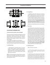
2. Remove the long bolts. Mount the disc packs
on the hubs with one bolt through the disc pack
aligned with a clearance hole in the hub. Install
the short bolts through the hub, disc pack, bevel
washer or link, and secure with a lockout.
NOTE: All bolt threads should be lubricated. A clean
motor oil is recommended. On size 226 and larger, a
link must be put on bolt rst. Remove the disc pack
alignment bolt. Proceed to mount the second disc
pack to the other hub in the same way.
3. Position one set of short bolts in each hub on
top. Now slide the center ring down into place
straddling the short bolts with the center ring
bushings. If coupling is dynamically balanced, the
center ring match marks must lineup with both
hub match marks. When one bushing is in-line
with the hole in the disc pack, slide one long bolt
through washer or link, disc pack, center ring,
disc pack, washer or link, and then secure with a
locknut. On size 226 and larger a link must be put
on the bolt rst. Now install the rest of the long
bolts in the same manner.
4. Torque the long bolt locknuts at this time.
Note: Alignment of C-Flange Units should be
checked when compressor or motor are replaced.
Installation