


38
2. Filter Removal and installation, all
VSR Units.
Release the pressure in the oil filter housing by
opening the bleed valves at the stop valve in the
block and bleed assembly, or at the bleed valve
for the oil filter housing. Be sure to follow all Lo-
cal, State and Federal ordinances regarding the
recovery of refrigerants.
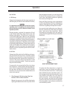
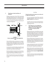
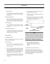
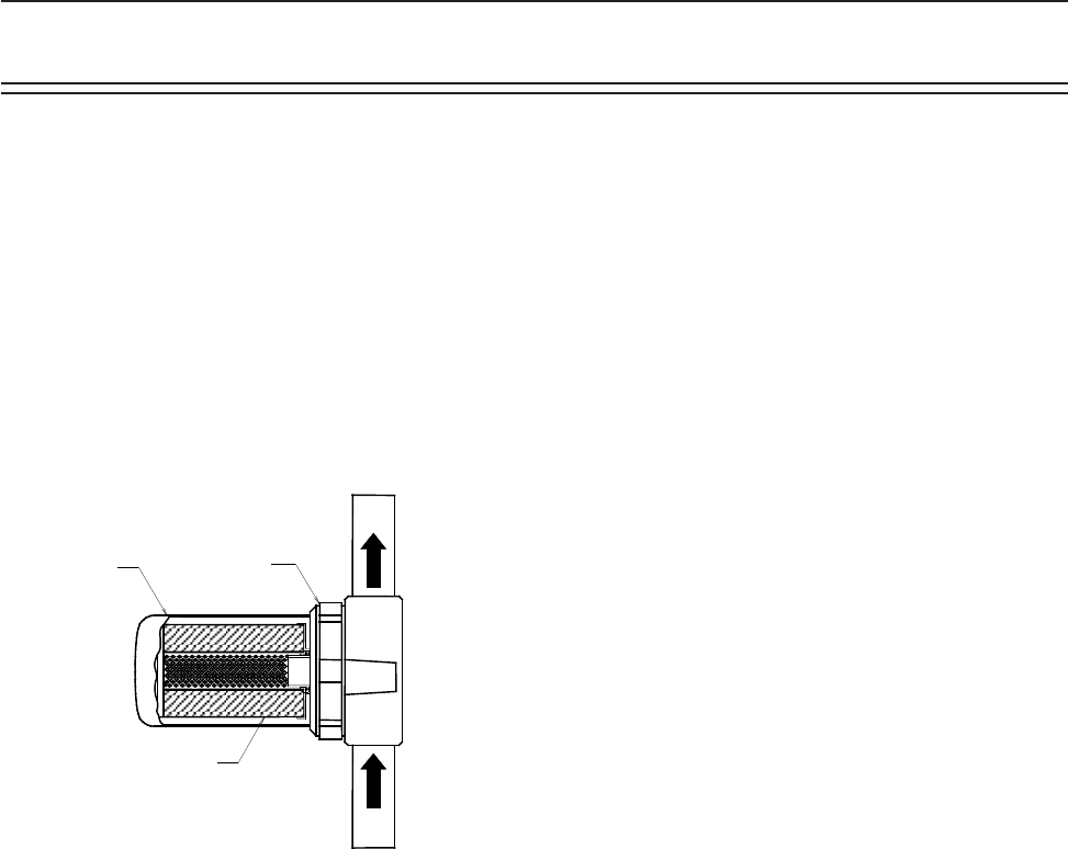
FIGURE 2.
TYPICAL CANISTER TYPE FILTER CROSS SEC-
TION
Drain the filter bowl or housing in to an appro-
priate container and dispose of the oil in a ap-
propriate manner following all Local, State and
Federal ordinances regarding the disposal of used
refrigeration oil.
Loosen and remove the locking ring on filter tank
by turning in a counter clockwise direction. Re-
move filter tank with the used element.
Remove the filter element from the tank. Be-
fore reassembling, thoroughly clean the tank to
lengthen the life span of the filter element.
Wet the threads and O-ring on the head and the
O-ring in the new element with clean refrigera-
tion oil.
CAUTION
Do not use a pipe wrench, hammer or any other tool
to tighten the locking ring.
nsert new element into the filter tank with
the open end visible. Attach tank to head and
HAND TIGHTEN the locking ring.
The filter housing can be evacuated and then
slowly pressurized to check for leaks before
returning to service.
3. Filter Removal, VSS and VSM Units
(after 5/1/00) when using Vilter Part
Numbers 3111A (16” Simplex), or
3112A (39” Simplex) oil filter
housings.
Release the pressure in the oil filter housing by
opening the bleed valves at the stop valve in
the block and bleed assembly, or at the bleed
valve for the oil filter housing. Be sure to follow
all Local, State and Federal ordinances regard-
ing the recovery of refrigerants.
Drain the filter bowl or housing in to an ap-
propriate container and dispose of the oil in a
appropriate manner following all Local, State
and Federal ordinances regarding the disposal
of used refrigeration oil.
Loosen and remove the cover on the bowl of
the filter tank by turning it in a counter clock-
wise direction. Remove the used element.
Wet the O-ring in the new element with clean
refrigeration oil. Insert the new element into
the filter tank with the closed end visible and
attach the cover to the bowl. HAND TIGHTEN
the cover.
The filter housing can be evacuated and then
slowly pressurized to check for leaks before
returning to service.
LOCKING
RING
FILTER
ELEMENT
FILTER
TANK
INLET
OUTLET
Operation