


42
A. Screw Compressor Control And Operation
1. Starting, Stopping and Restarting the Com-
pressor.
Before the screw compressor unit is started,
certain conditions must be met. All of the
safety setpoints must be in a normal condition,
and the suction pressure must be above the
low suction pressure setpoint to assure that a
load is present. When the “On-Off” switch or
“Manual-Auto” button is pressed, the oil pump
will start. When sufficient oil pressure is built
up and the compressor capacity control and
volume ratio slide valves are at or below 10%,
the compressor unit will start.
If the compressor is in the automatic mode, it
will now load and unload and vary the volume
ratio in response to the system demands.
Stopping the compressor unit can be accom-
plished a number of ways. Any of the safety
setpoints will stop the compressor unit if an
abnormal operating condition exists. The com-
pressor unit “On-Off” or stop button will turn
the compressor unit off as will the low pressure
setpoint. If any of these conditions turns the
compressor unit off, the slide valve motors will
immediately energize to drive the slide valves
back to 5% limit. The control motors will be
de-energized when the respective slide valve
moves back below 5%. If there is a power failure,
the compressor unit will stop. If the manual
start on power failure option is selected (see ap-
propriate Microprocessor Instruction Manual),
restarting from this condition is accomplished
by pushing the reset button to insure positive
operator control. If the auto start on power fail-
ure option is selected (see appropriate Micro-
processor Instruction Manual), the compressor
unit will start up after a waiting period. With
both options, the compressor slide valves must
return below their respective 5% limits before
the compressor unit can be restarted.
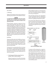
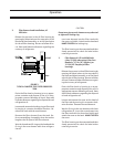
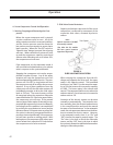
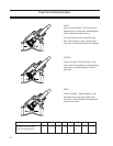
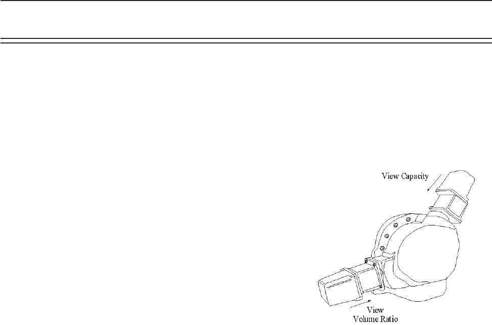
2. Slide Valve Control Actuators
Capacity and volume ratio control of the screw
compressor is achieved by movement of the
respective slide valves, actuated by electric
motors.
FIGURE 4.
SLIDE VALVE MOTOR LOCATION
When viewing the compressor from the dis-
charge end (opposite the drive end), the upper
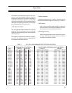
motor is for capacity control. The command
shaft turns (see Table 1) to decrease the capac-
ity to 10% and reverses to increase the capacity
to 100%. The lower motor is for volume ratio
control. The command shaft turns to reduce the
volume ratio to 2.0, and reverses to increase the
volume ratio to 5.0.
Actuation of the electric motors can be done
manually or automatically. To actuate the mo-
tors manually, place the desired mode selector
in the manual position and push the manual
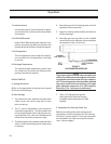
Increase or Decrease buttons. In the automatic
mode, the microprocessor determines the direc-
tion to actuate the electric motors. However,
in the automatic mode, there is an “On” and
“Off” time for the capacity control motor. The
“On” time is the time in which the slide valve
moves, and the “Off” time is the time in which
the system is allowed to stabilize before another
change in slide valve position.
Operation
Note:
Optical Actuators CAN NOT
be manually rotated.
(The VSM 501-701 models
will have motor locations
oppositeofgure#6)