54
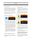
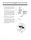
E) Remove the hex head and socket head bolts from
the thrust bearing cover. Insert two of the bolts
into the threaded jacking holes to assist in remov-
ing the cover. Retain the shim pack and keep it
with the bearing housing cover.
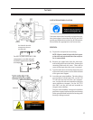
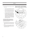
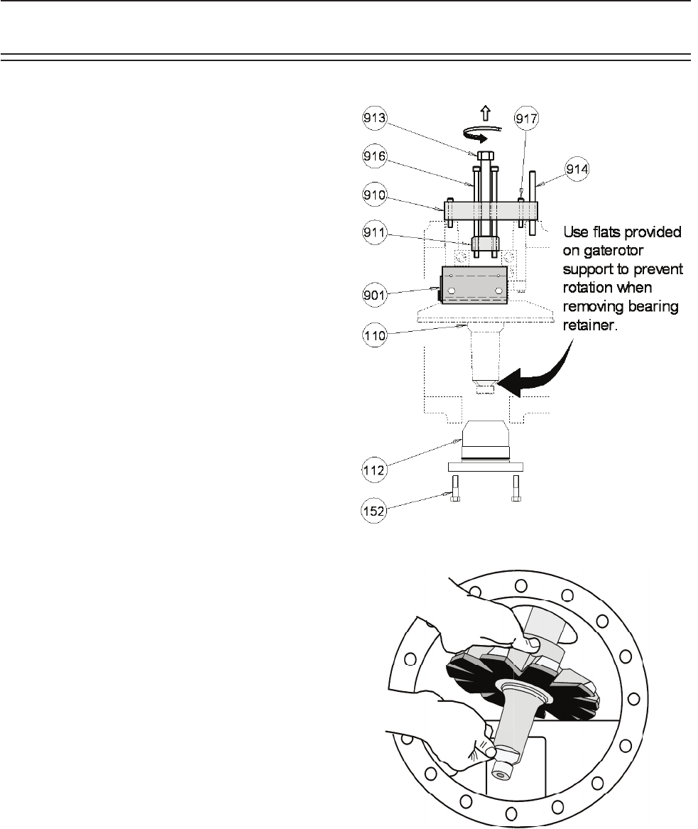
F) Hold the gate rotor support with a suitable wrench
on the ats provided near the roller bearing hous-
ing. Remove the inner retainer bolts and the
retainer. To remove the thrust bearing housing,
install the thrust bearing removal and installation
tool with the smaller puller shoe. Turn the jacking
screw clockwise. The thrust bearings and housing
assembly will be pulled off the shaft and out of the
frame.
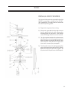
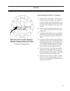
G) Remove the bolts on the roller bearing housing.
Thread two bolts into the jack screw holes pro-
vided in the housing to assist in removing it.
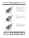
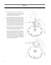
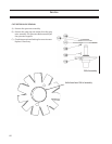
H) To remove the gate rotor support, carefully move
the support opposite the direction of rotation and
tilt the roller bearing end towards the suction end
of the compressor. The compressor input shaft
may have to be turned to facilitate the removal of
the gate rotor support. On dual gate compressor
units, repeat the procedure for the remaining gate
rotor support assembly.
Service


