


47
Field Wiring Requirements
VRS SCREW COMPRESSOR, VSS/VSM SINGLE SCREW COMPRESSOR UNITS
PRESTART-UP CHECKLIST
FIELD WIRING REQUIREMENTS FOR UNITS WITH FACTORY WIRED VISSION
®
MICROPROCESSORS
NOTE: If startup service has been purchased, to save time and money, the following items should be completed
before the startup technician arrives.
The unit is pre-wired at the factory. The necessary field wiring connections are described below.
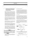
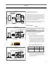
1. Control power of 115 VAC 50/60 HZ must be wired to the left side terminals of the digital I/O board inside
the ViSSion
®
cabinet. Line power (L1) is brought in to a 10-amp fuse via the terminal marked “L1” on the
appropriate connector. The neutral (L1A) is brought in and connected to any of the “N” terminals located
on left connectors. Two separate line power feeds for the oil heaters are brought to two additional 10
amp fuses via the terminals marked “L2” and “L3” on the same connector just below the “L1” terminal.
The neutrals for these circuits (L2A and L3A) are also connected to any of the “N” terminals. For units
with V-PLUS
®
oil cooling, L1 must also be brought to the fuse in the V-PLUS® panel, and L1A must also be
brought to the terminal #2B in the V-PLUS
®
panel.
2. An auxiliary contact from the compressor motor starter is required. This isolated contact is connected to
the K-1 input relay using any of the “L” terminals on the strip of connectors, and returned to the terminal
marked “Motor Starter Aux. Safety” at the very top connector.
3. A dry contact from control relay K-22 must be wired to the compressor motor starter coil. This dry contact
is wired to terminals marked “Compressor Start – N.O. #1A” and “Compressor Start – N.O. #1B”. Control
power for this coil should come from a source, which will be de-energized with the compressor disconnect.
4. A dry contact from control relay K-19 must be wired to the oil pump motor starter coil. This dry contact
is wired to the two terminals marked “Oil Pump Starter”. Control power for this coil should come from a
source, which will be de-energized with the compressor disconnect.
5. An auxiliary safety cutout is available to shut down the compressor package using the K-2 input relay. A
dry contact must be supplied and wired to one of the “L” terminals on any of the connectors, and returned
to the terminal marked “Auxiliary #1 Safety” at the top connector. The jumper to the “Auxiliary #1 Safety”
terminal must be removed to use this cutout. The contact, if closed, will allow the compressor to run. If
this contact opens at any time, the compressor will shut down.
6. Indication of the compressor alarm or shutdown status is also available via two control relays. Relay K-20
is provided for remote trip indication and relay K-21 is provided for remote alarm indication. Each relay
has three terminals available: a common input, a normally open contact, and a normally closed contact.
For both relays, the energized state represents a “trip” or “alarm” condition. Loss of voltage to the relay
coil and the resultant return to normal state indicates “safe” condition.
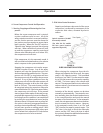
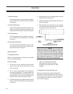
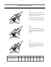
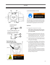
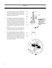
7. The current transformer supplied in the compressor motor conduit box should be checked to insure that
the motor leads of one leg are pulled through the transformer. Note that there is a dot on one side of the
current transformer. This dot must face away from the motor. Typically, a wye delta started motor should
have leads 1 and 6 pulled through this transformer for a 6 lead motor. However, this should always be
checked as different motors and starting methods will require different leads to be used.
Order #_______________________________Compressor Serial #________________________